
Phase-modified quasi-non-diffracting laser beams for high angle laser processing of transparent workpieces

a laser beam and high angle technology, applied in glass making apparatus, manufacturing tools, welding/soldering/cutting articles, etc., can solve problems such as prone to breakage of square separated edges, induced absorption of glass dust and particles, and defectes in transparent workpieces

Active Publication Date: 2020-11-19
CORNING INC
View PDF11 Cites 15 Cited by
  • Summary
  • Abstract
  • Description
  • Claims
  • Application Information

AI Technical Summary

Benefits of technology

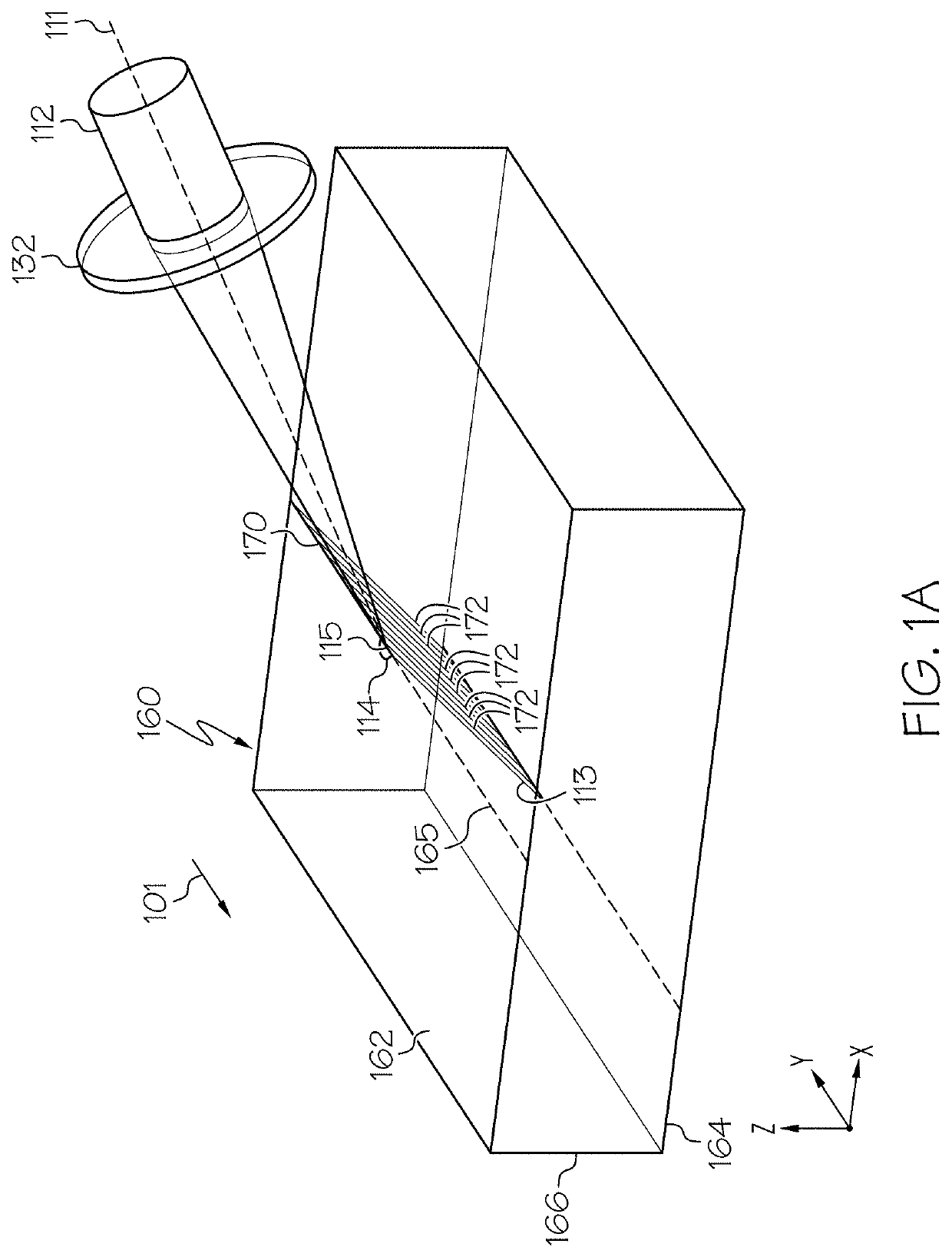
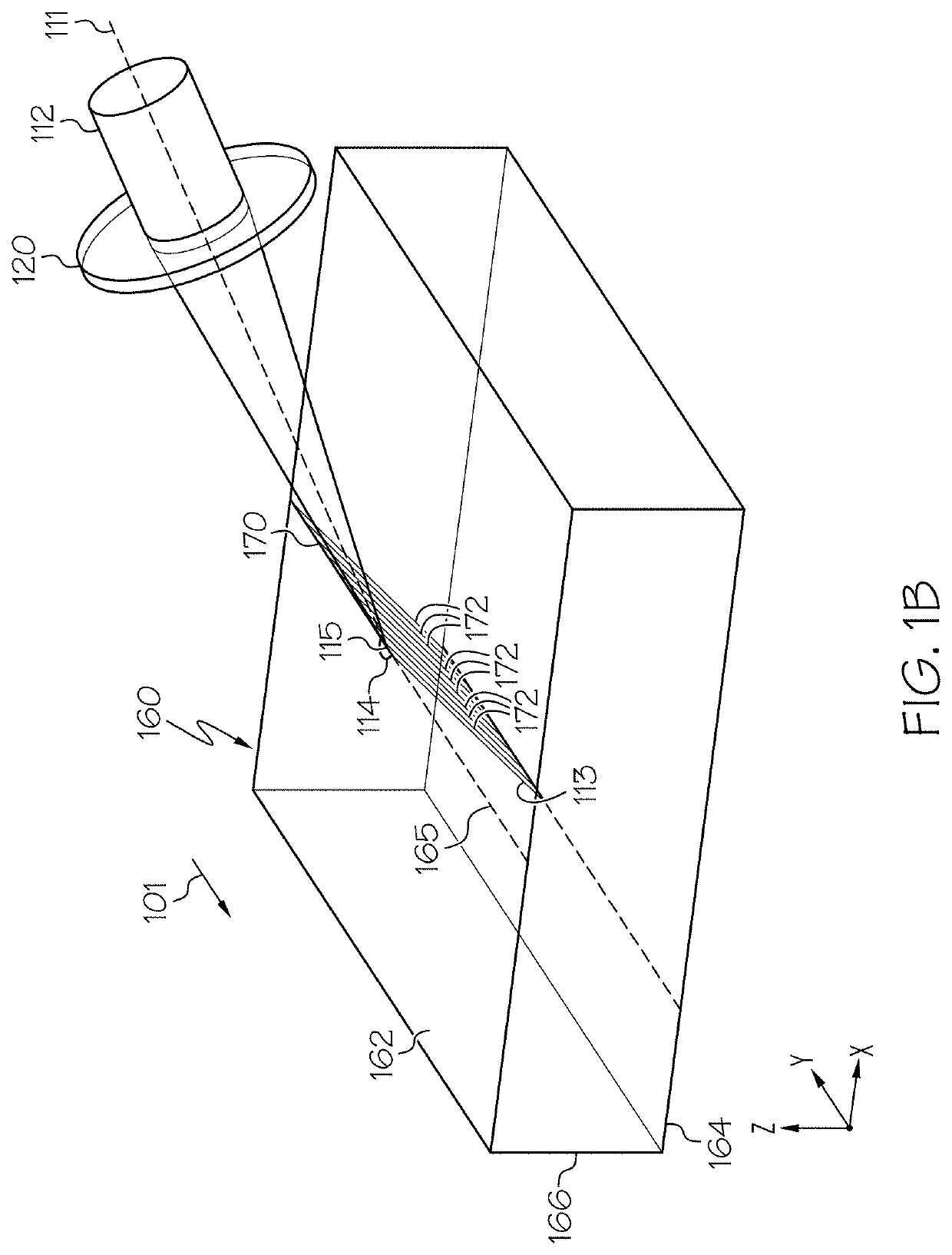
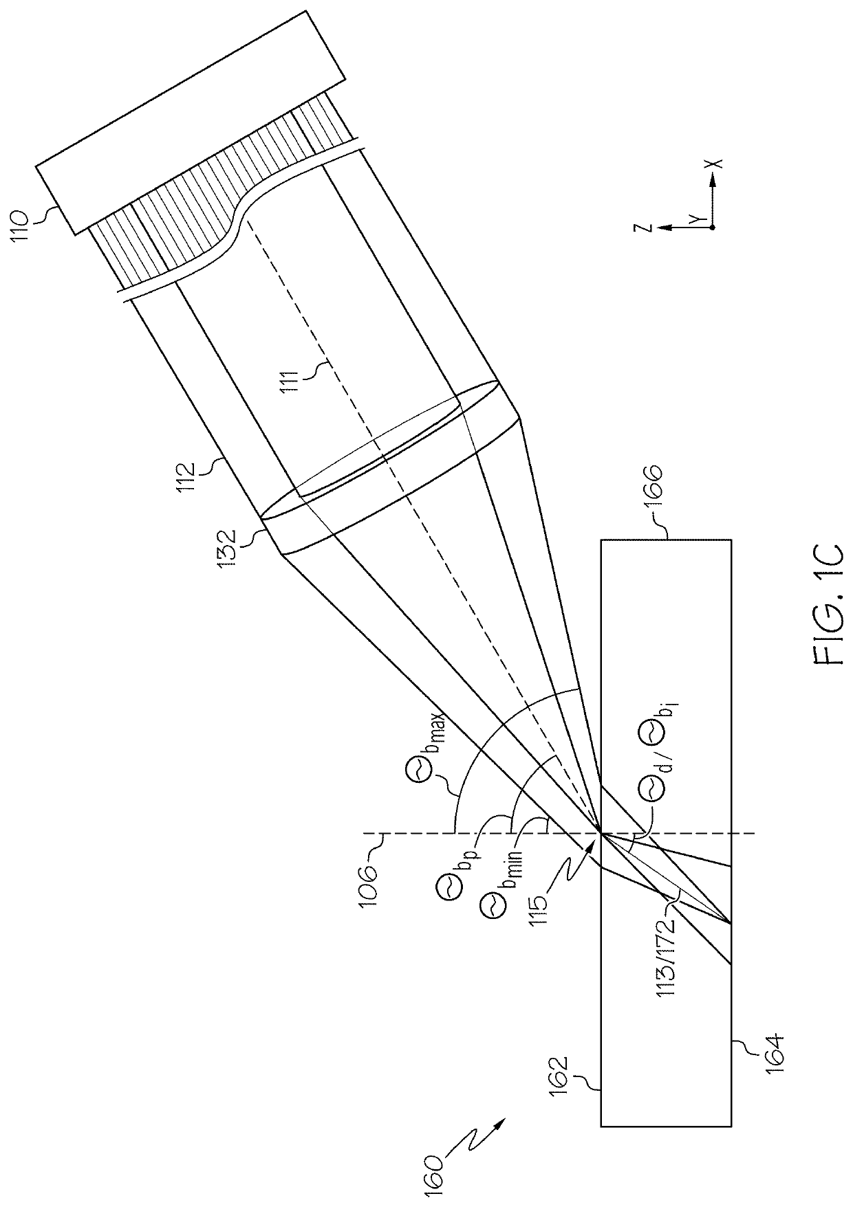
This patent is about a method for processing transparent workpieces using a laser beam. The laser beam is directed into the workpiece to form a laser beam focal line that generates an induced absorption, resulting in a defect. The laser beam has an oblong angular spectrum with an axis of symmetry and a non-circular angular spectrum when incident on a non-planar surface. The laser beam can also be refracted at the surface. Overall, the method and system described in this patent allow for precise laser processing of transparent workpieces.

Problems solved by technology

Many methods of separating glass substrates result in square separated edges that are prone to breakage and are often processed to have bevels or to be rounded to minimize the chance of breakage.
However, the processes generate glass dust and particles, which must be cleaned by additional process steps involving washing or chemical treatments.
The induced absorption produces a defect within the transparent workpiece.

Method used


Image

  • Phase-modified quasi-non-diffracting laser beams for high angle laser processing of transparent workpieces
  • Phase-modified quasi-non-diffracting laser beams for high angle laser processing of transparent workpieces
  • Phase-modified quasi-non-diffracting laser beams for high angle laser processing of transparent workpieces

Examples


examples

[0134]Referring now to FIGS. 10A-10C, by way of comparative example, a Bessel beam (one type of quasi-non-diffracting beam) having a circular angular spectrum upstream and / or incident the impingement surface (such as in free space) focused into a laser beam focal line having an internal beam angle θbi of 15° is shown, as a cross section, at the impingement surface of the transparent workpiece 160 (FIG. 10A), at a depth of 0.3 mm from the impingement surface (FIG. 10B), and at a depth of 0.7 mm from the impingement surface (FIG. 10C). While the laser beam focal line has minimal aberrations at the impingement surface of the transparent workpiece (FIG. 10A), the Bessel beam having a circular angular spectrum upstream and / or incident the impingement surface (such as in free space) and focused into a laser beam focal line becomes increasingly aberrated as it propagates through the transparent workpiece, as shown in FIG. 10B and FIG. 10C. Further, FIG. 10D depicts an example image of a da...


PUM

PropertyMeasurementUnit
defect angleaaaaaaaaaa
angleaaaaaaaaaa
depthaaaaaaaaaa

Abstract

A method for processing a transparent workpiece that includes directing a laser beam the transparent workpiece. The laser beam incident to the impingement surface has an oblong angular spectrum and portion of the laser beam directed into the transparent workpiece is a laser beam focal line and generates an induced absorption to produce a defect within the transparent workpiece. The laser beam focal line includes a wavelength λ, a spot size wo, a Rayleigh range ZR that is greater thanFDπwo2λ,where FD is a dimensionless divergence factor comprising a value of 10 or greater, and an internal beam angle of greater than 10° relative to a plane orthogonal to an impingement surface at an impingement location, such that the defect has a defect angle within the transparent workpiece of greater than 10° relative to a plane orthogonal to the impingement surface at the impingement location.

Description

[0001]This Application claims priority under 35 USC § 119(e) from U.S. Provisional Patent Application Ser. No. 62 / 849,364, filed on May 17, 2019, and which is incorporated by reference herein in its entirety.BACKGROUNDField[0002]The present specification generally relates to apparatuses and methods for laser processing transparent workpieces, and more particularly, to laser beams comprising laser beam focal lines that are quasi-non-diffracting and retain a quasi-non-diffracting character when directed into a transparent workpiece at a non-normal angle of incidence.Technical Background[0003]The area of laser processing of materials encompasses a wide variety of applications that involve cutting, drilling, milling, welding, melting, etc. of different types of materials. Among these processes, one that is of particular interest is cutting or separating different types of transparent substrates in a process that may be utilized in the production of materials such as glass, sapphire, or ...

Claims


Application Information

Patent Timeline
Patent Type & Authority Applications(United States)
IPC IPC(8): B23K26/38B23K26/073B23K26/359
CPCB23K26/073B23K26/359B23K26/38C03B33/0222B23K26/53B23K26/0738B23K2103/54
Inventor IVANOV, VIACHESLAV VIACHESLAVOVICHKALITEEVSKIY, NIKOLAY ALEKSEYEVICHSAVIDIS, NICKOLAOSSTERLINGOV, PETR MIKHAYLOVICHTERBRUEGGEN, RALF JOACHIMUNGARO, CRAIG JOHN MANCUSI
Owner CORNING INC
Learn More