
Compound two-way antenna with installation compensator

Active Publication Date: 2009-08-06
INTEL CORP
View PDF2 Cites 40 Cited by
  • Summary
  • Abstract
  • Description
  • Claims
  • Application Information

AI Technical Summary

Benefits of technology

[0006]In a first aspect the present invent the provides an antenna system comprising an antenna support structure, an antenna including one or more radiating elements, and an antenna mounting structure coupling the antenna to the antenna support structure, the antenna mounting structure including a movable mount allowing

Problems solved by technology

When a two-way antenna is installed on a non-vertical support the effective coverage area offered by such antenna is no longer uniform, depending on azimuth and down tilt settings as commanded by network operator.
This causes a difficulty in providing the desired coverage in a consistent manner due to unpredictable installation variations.

Method used


Image

  • Compound two-way antenna with installation compensator
  • Compound two-way antenna with installation compensator
  • Compound two-way antenna with installation compensator

Examples


Embodiment Construction

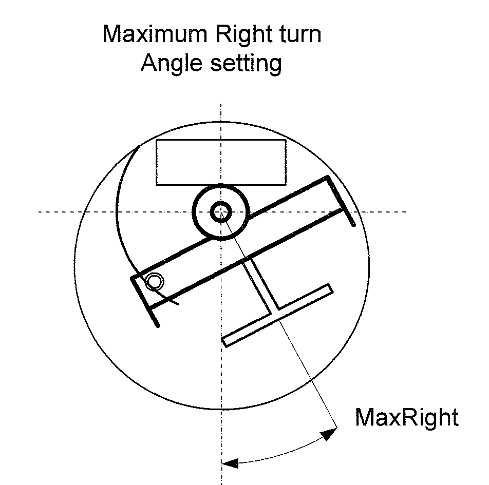
[0018]The present invention provides an antenna system and method with uniform or compensated sector coverage by monitoring tri-vector gravitational inclinometer and earth magnetic field, determining correction factors for antenna tilt and azimuth beam adjustments. Optionally, azimuth antenna beamwidth can be compensated in addition to antenna down tilt angle and azimuth direction of antenna beam. The latter can be used with a three-way antenna. In preferred embodiments of the present invention, tri-vector gravitational inclinometer and earth magnetic field sensors are provided together with a microprocessor for calculating correction factors for the two-way antenna control parameters.

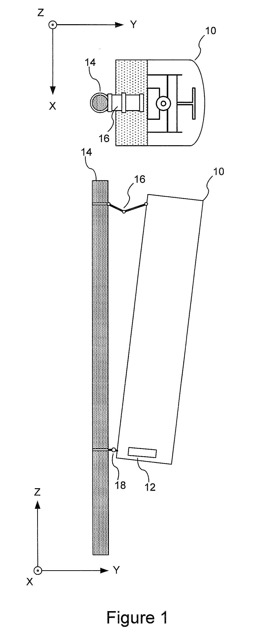
[0019]FIG. 1 shows a top and a side view of an antenna array (10) enclosed in a suitable radome according to an exemplary implementation of the present invention, which utilizes an antenna position sensor module, APS, (12) for determining antenna inclination and azimuth angle based on earth's magnetic ...


PUM


Abstract

A two-way terrestrial antenna, employing electrical down tilt and azimuth beam adjustment capability is disclosed. Such antenna configuration allows for a variable antenna coverage footprint within designated coverage sector. To compensate for installation support structure variations the two-way antenna employs a positional sensor that can provide feedback to BTS or automatically compensate azimuth and tilt beam angles so as to provide uniform sector coverage. In particular by monitoring tri-vector gravitational inclinometer and earth magnetic field sensors, and determining correction factors for antenna tilt and azimuth beam adjustments, uniform or compensated sector coverage is provided.

Description

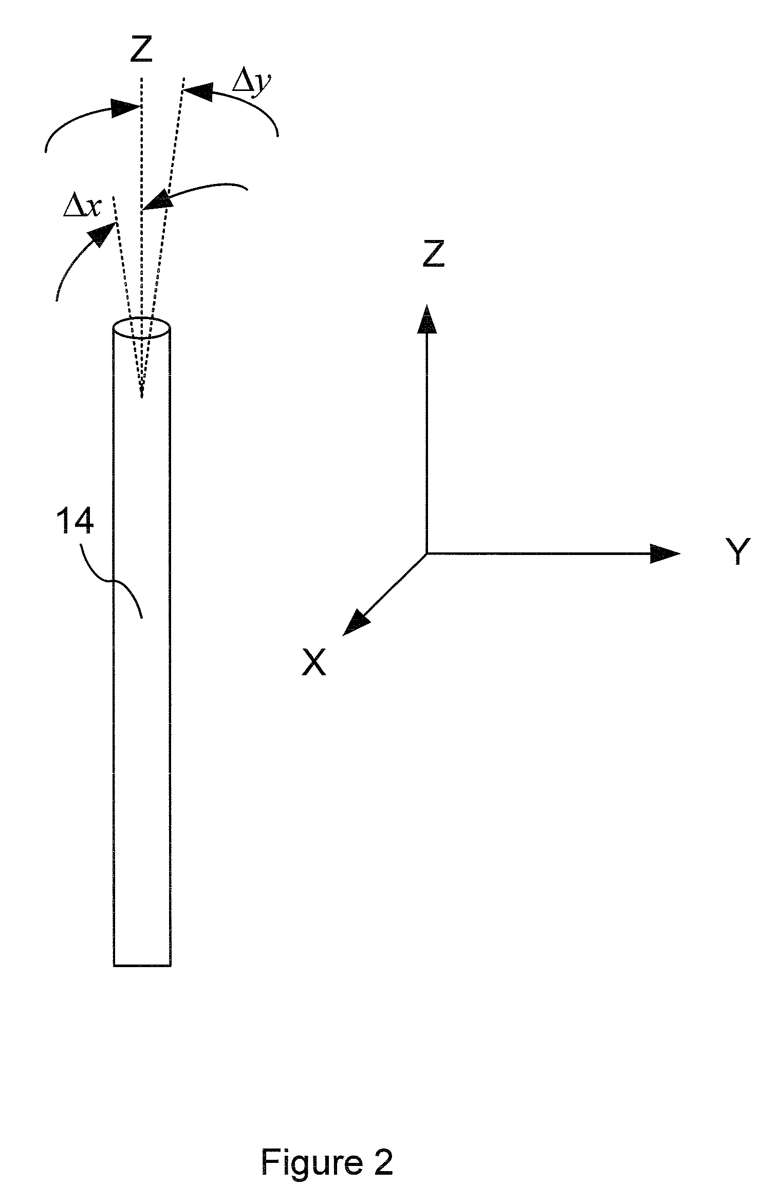
RELATED APPLICATION INFORMATION[0001]The present application claims the benefit under 35 USC 119(e) of U.S. provisional patent application Ser. No. 61 / 063,215 filed Feb. 1, 2008, the disclosure of which is incorporated herein by reference in its entirety.BACKGROUND OF THE INVENTION[0002]1. Field of the Invention[0003]The present invention relates in general to communication systems and components, and related methods. More particularly the present invention is directed to antenna systems for wireless communication networks.[0004]2. Related Background Information[0005]The coverage area offered by an antenna in a wireless communication network is dependent on the installation facilities, for example antenna tower, or other suitable support structure. In less than ideal circumstances such antenna support structure may have a mounting surface which is not vertical—i.e. having a compound angle deviation from vertical z-axis. When a two-way antenna is installed on a non-vertical support t...

Claims


Application Information

Patent Timeline
IPC IPC(8): H01Q3/08H01Q1/12
CPCH01Q3/08H01Q1/1228
Inventor VASSILAKIS, BILLMASLENNIKOV, NIKOLAIRABINOVICH, ALEXANDER
Owner INTEL CORP
Learn More