
Beam forming with focus location adjustment

a beam intensity profile and beam technology, applied in the field of projection lenses, can solve the problems of reducing the beam intensity profile at the focus, affecting the accuracy of beam intensity profiles, so as to reduce the degradation of beam intensity profiles

Active Publication Date: 2020-10-29
COHERENT INC
View PDF0 Cites 3 Cited by
  • Summary
  • Abstract
  • Description
  • Claims
  • Application Information

AI Technical Summary

Benefits of technology

The patent describes a device that can move the focus of a laser beam without making the beam weaker. The device has a beam source, optics that form the beam, and two lenses that focus the beam. A translator moves the second lens in front of the beam forming optics and the first lens, which changes the direction of the beam. This allows the beam to be shone in a new position. This device can be used in various applications that require precise shining of a laser beam.

Problems solved by technology

Particles scatter radiation and emit radiation based on the intensity of the laser light at the focus; variations in intensity at the focal point can lead to variations in scattering and emission, which can cause erroneous measurements.
If intensity varies, scattering and emission will vary, and thus detectors will fail to consistently identify the same particle type: a particle may or may not be detected depending on its position in the flow.
Beam focus movement can cause degradation of beam intensity profile at the focus.
Focal point adjustment, however, can alter the beam intensity profile and thereby negatively impact effectiveness of the laser application.

Method used


Image

  • Beam forming with focus location adjustment
  • Beam forming with focus location adjustment
  • Beam forming with focus location adjustment

Examples


Embodiment Construction

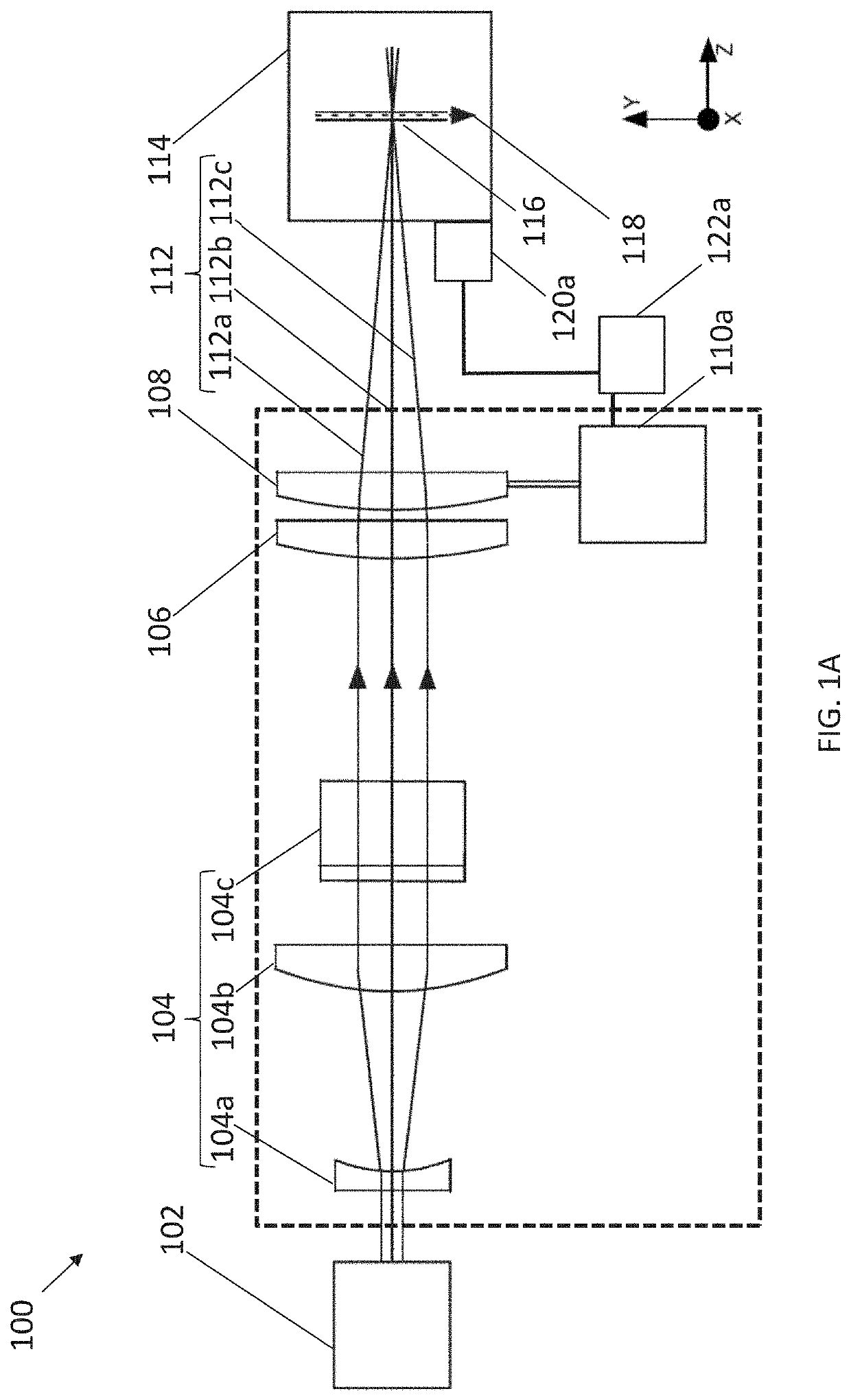
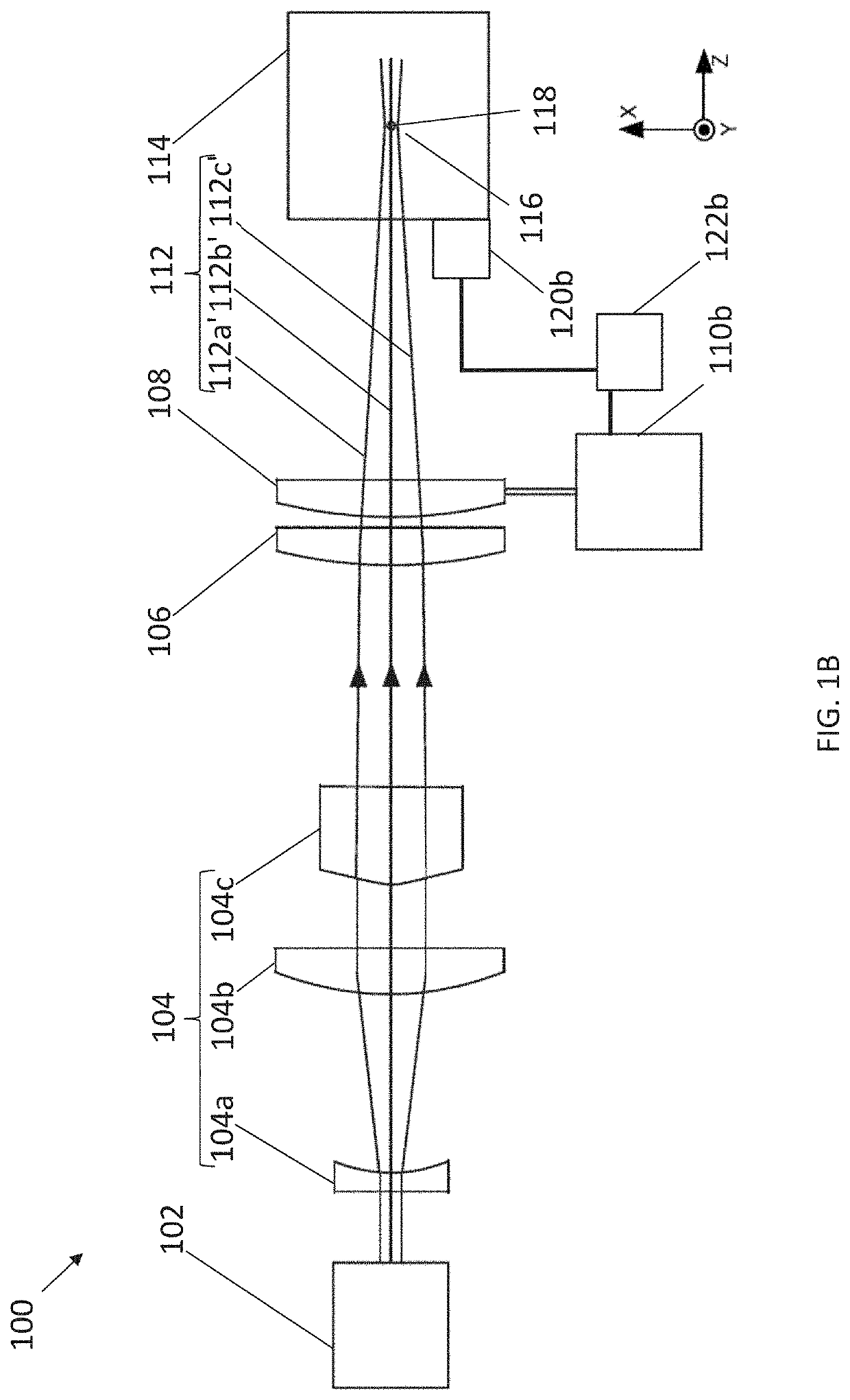
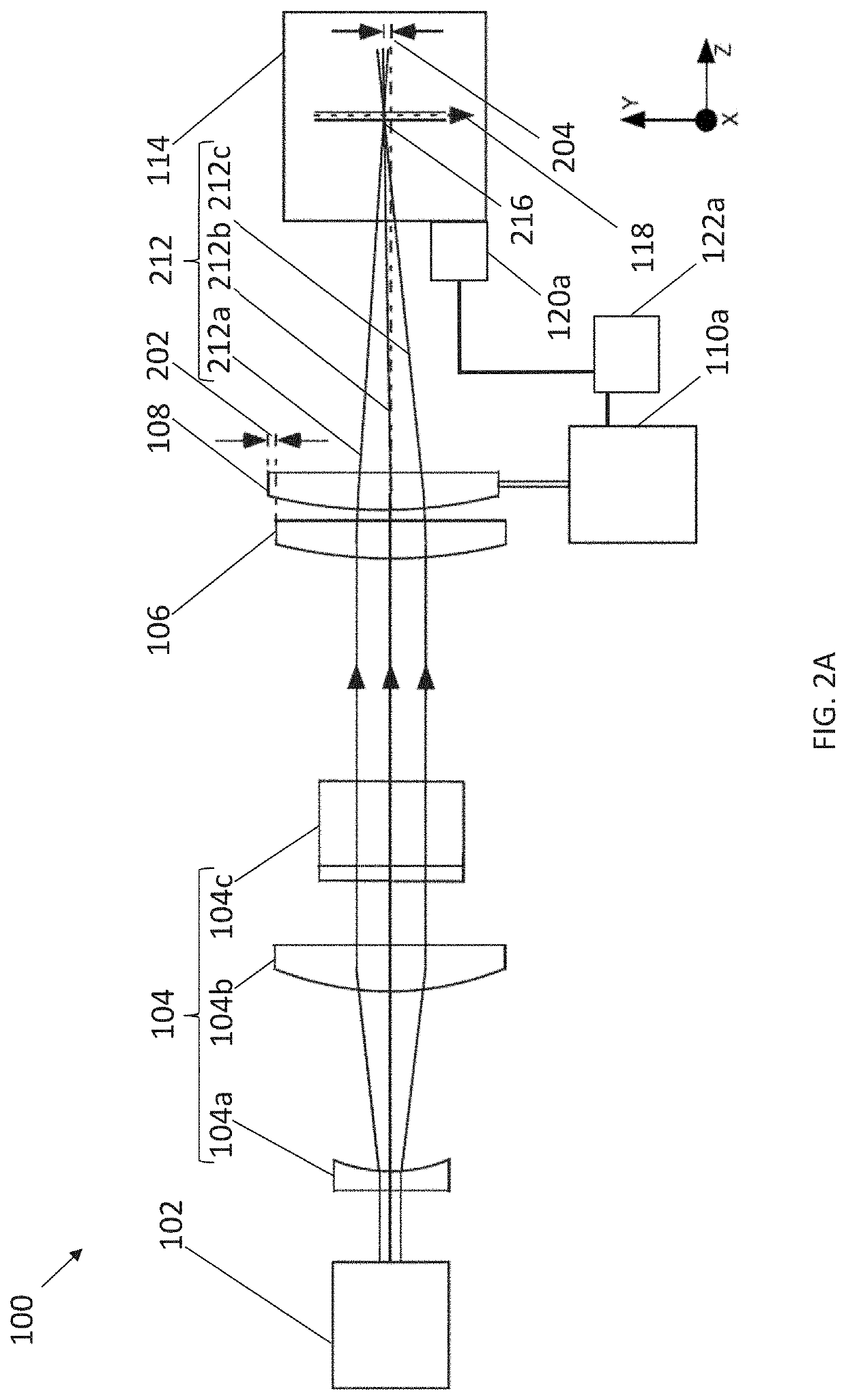
[0015]Turning now to the drawings, wherein like features are designated by like reference numerals, FIG. 1A is a side-view schematically illustrating apparatus 100 for focusing a laser beam in accordance with an embodiment of the present invention. Apparatus 100 includes beam source 102 producing beam 112, beam forming optics 104, a first focusing lens 106, a second focusing lens 108, a lens translator 110a, and (optional) sensor 120a. Beam 112 is depicted by center ray 112b and peripheral rays 112a and 112c. Beam forming optics 104 are positioned between the beam source 102 and the first focusing lens 106, and first focusing lens 106 is positioned between beam forming optics 104 and second focusing lens 108.

[0016]The beam forming optics 104, the first focusing lens 106, and the second focusing lens 108 are arranged to receive the beam 112 of laser radiation from the beam source 102 and to form the beam 112 into an elongated focus 116. FIG. 1A depicts the short axis of the elongated...


PUM

PropertyMeasurementUnit
Fractionaaaaaaaaaa
Fractionaaaaaaaaaa
Fractionaaaaaaaaaa

Abstract

An apparatus includes a beam source, beam forming optics, a first focusing lens having a focal length, a second focusing lens having a focal length similar to the focal length of the first lens, and a lens translator configured to move the second lens transversely relative to the beam forming optics and to the first lens, and thereby move the elongated focus transversely. In some embodiments, the beam forming optics are positioned between the beam source and the first focusing lens, the first focusing lens is positioned between the beam forming optics and the second focusing lens, and the beam forming optics, the first focusing lens, and the second focusing lens are arranged to receive a beam of laser radiation from the beam source and to form the beam into an elongated focus.

Description

TECHNICAL FIELD OF THE INVENTION[0001]The present disclosure relates in general to projection lenses. In particular, disclosed herein are apparatuses and methods for reduced degradation of beam intensity profile when repositioning the beam's focus.DISCUSSION OF BACKGROUND ART[0002]A basic principle of flow cytometry is the passage of particles in a fluid-stream through a focused beam of laser-radiation. The particles, particularly biological cells, can be detected, identified, counted, and sorted. Cell components are fluorescently labelled and then illuminated by the laser-radiation. Scattered and emitted radiation can be measured to determine the quantity and types of cells present in a sample.[0003]Several detectors are carefully placed around the point where the fluid-stream passes through the focused laser-beam. The suspended particles, which may range in size from 0.2 to 150 micrometers (μm), pass through the focused laser-beam and scatter the laser-radiation. The fluorescently...

Claims


Application Information

Patent Timeline
IPC IPC(8): G02B27/09G02B27/16
CPCG02B27/16G02B27/095G02B27/0927G01N15/1459G02B26/0875G02B27/0911G02B27/0955B23K26/0738B23K26/0648G01N2015/1452G01N15/1434G01N2015/1006B23K26/082B23K26/032B23K26/0732
Inventor MENG, LEIWINZ, MICHELE WAYNE
Owner COHERENT INC
Learn More