
Jet mill

Active Publication Date: 2020-10-22
ALBUS JAMES F
View PDF0 Cites 0 Cited by
  • Summary
  • Abstract
  • Description
  • Claims
  • Application Information

AI Technical Summary

Benefits of technology

The patent describes a new type of jet mill that can make fine particles of solid material. The jet mill has a cylindrical structure with a large surface area that helps to reduce the size of particles. The particles collide with each other and with the wall of the jet mill, resulting in more efficient and effective size reduction compared to other jet mills. This makes it possible to produce fine particle distributions that are important for pharmaceutical and biopharmaceutical products.

Problems solved by technology

Conventional axial jet mills, lack the ability to achieve efficient reduction of particles to the fine particle sizes required in modern pharmaceutical and biopharmaceutical products.
In the case of larger diameter axial jet mills, the particles rapidly move inward to locations remote from the nozzles, where the kinetic energy of the gas streams exiting from the nozzles is insufficient to produce fine particles.
Smaller diameter axial jet mills, on the other hand, can achieve better particle size reduction, but are less efficient because of their inability to process large volumes of material.

Method used


Image

  • Jet mill

Examples


Embodiment Construction

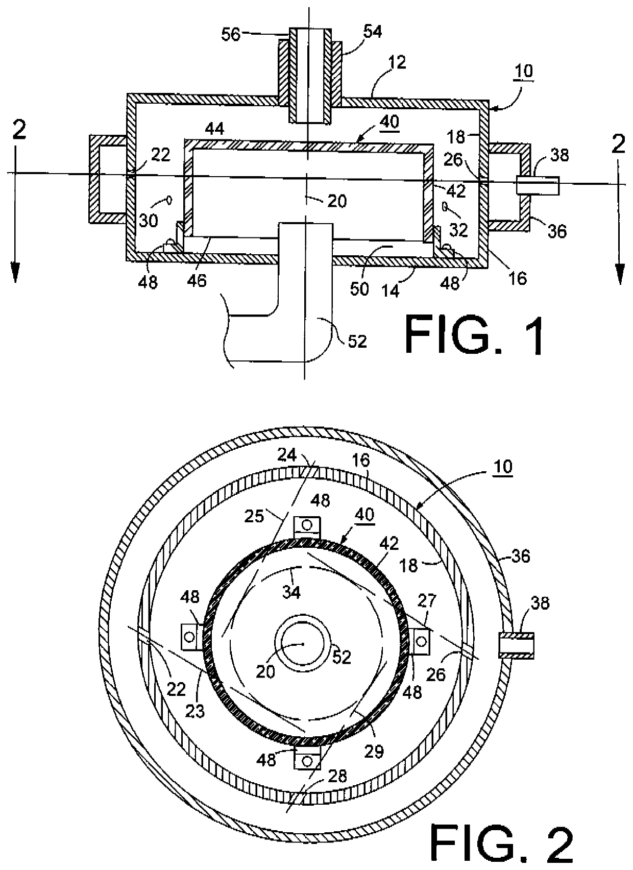
[0015]As shown in the drawings, the jet mill in accordance with the invention includes a housing 10 having a top wall 12, a bottom wall 14 and a vertical outer wall 16 having a substantially circular, cylindrical inner surface 18 having a central axis 20, from which surface 18 is uniformly spaced. Typically the jet mill will be arranged so that the central axis is vertical. However the jet mill can be operated in other orientations. The wall 16 of the housing is provided with a set of openings distributed around its perimeter. These openings serve as nozzles for directing jets of gas into a raceway inside the housing. Four such openings, 22, 24, 26 and 28, are shown in FIG. 2. Openings 22 and 26 are also visible in FIG. 1. Openings 22, 24, 26 and 28 are at the same level. These nozzles are spaced at 90° intervals on the perimeter of vertical wall 16. Additional openings 30 and 32, located at a level below the level of openings 22-28 are visible in FIG. 1. Openings 30 and 32 are spac...


PUM


Abstract

In an axial jet mill, an internal structure having a cylindrical outer surface is positioned within a housing to establish a raceway for the circulating movement of gas and solid material while maintaining the gas and solid material in close proximity to the outlets of gas nozzles distributed around the perimeter of the raceway. Solid material enters the jet mill though a bottom wall of the housing and passes into the raceway though gaps between the bottom of the internal structure and a bottom wall of the housing. Particles and gas exit the jet mill though a central outlet in the housing located above the internal structure.

Description

CROSS-REFERENCE TO RELATED APPLICATION[0001]This application claims the benefit, under 35 USC § 119(e), of U.S. Provisional Patent Application No. 62 / 829,352, filed Apr. 4, 2019.FIELD OF THE INVENTION[0002]This invention relates to jet mills for reducing the size of solid particles and particularly to improvements in so-called “axial” or “spiral” jet mills, i.e., jet mills in which gas jets distributed about the perimeter of a housing cause the solid particles to circulate within the housing about a central axis, and in which particles exit from the housing at a central location along the direction of the central axis.BACKGROUND OF THE INVENTION[0003]U.S. Pat. No. 2,032,827, granted on Mar. 3, 1936, describes a jet mill for pulverization and for providing material in finely divided form. The jet mill includes a housing having a circular, cylindrical, vertical wall with a multiplicity of angularly spaced nozzles arranged to release gaseous fluid at a high velocity in directions tange...

Claims


Application Information

Patent Timeline
IPC IPC(8): B02C19/06
CPCB02C19/061
Inventor ALBUS, JAMES F.
Owner ALBUS JAMES F
Learn More