
System and Method for Calibration of Hydraulic Models by Surface String Weight

a hydraulic model and string weight technology, applied in the field of system and method for calibration of hydraulic models by surface string weight, can solve the problems of affecting the accuracy of hydraulic models, etc., and achieves the effect of difficult to predict accurately

Active Publication Date: 2020-10-01
GRANT PRIDECO LP
View PDF0 Cites 0 Cited by
  • Summary
  • Abstract
  • Description
  • Claims
  • Application Information

AI Technical Summary

Benefits of technology

The patent text discusses the factors that affect the density of mud used in drilling oil wells. The first term is the hydrostatic pressure gradient, which is a function of both pressure and temperature. Compressibility and thermal expansion can cause the mud density to change with depth. The text also simplifies the case where the string is rotating off bottom without any axial motion and shows how the tension at the top of the string can be calculated. The main technical effect of the patent text is to provide a method for accurately predicting the mud density in drilling oil wells, which can help improve the efficiency of drilling operations.

Problems solved by technology

Many which the formation is damaged, and the drilling mud tends to flow into cracks in the formation.
Violation of these limits leads to situations commonly called loss and kick, respectively.
Both situations are dangerous and can, if not handled quickly and properly, lead to disastrous blowouts.
The dynamic pressure is far more difficult to determine, and it must be calculated from very uncertain hydraulic models.
Often none of these options are available for the driller, implying that he / she needs to rely solely on the hydraulic models when estimating the downhole pressure under different conditions

Method used


Image

  • System and Method for Calibration of Hydraulic Models by Surface String Weight

Examples


Embodiment Construction

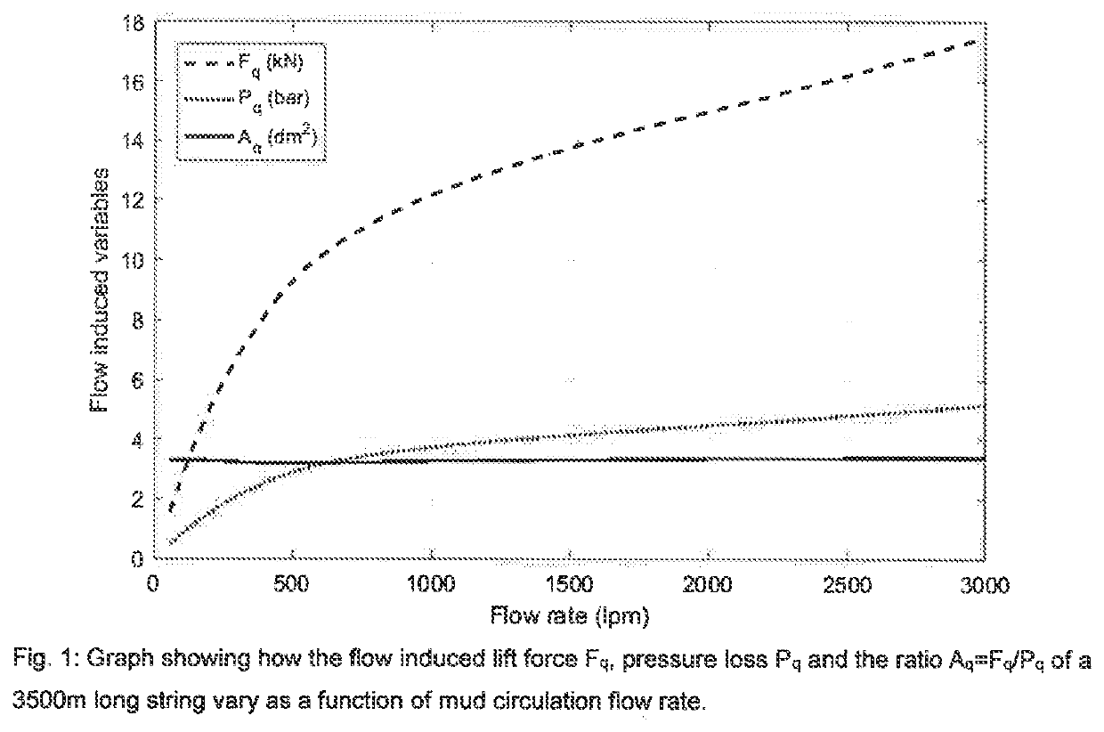
"d_n">[0035]Reference is made to FIG. 1 showing how the flow induced lift force Fq, the pressure loss Pq and the ratio Aq=Fq / Pq of the above string vary as a function of mud circulation flow rate. The hydraulic model used for calculating these curves is more advanced than the mentioned API model. The curves are calculated for a typical non-Newtonian mud commonly used in the drilling industry and the gradients include the effect of reduced cross section at the tool joints. In contrast to the API model, the applied model also includes the relatively weak effect of drill string rotation and the plotted curves are calculated with a string rotation speed of 60 rpm. Further comments to the theoretic results in the reference figure are the following.

[0036]The non-linearity causing the variable slope of both the force and pressure curves comes from the non-linear rheology characteristics of the mud, which follows the well-known Herschel-Bulkley rheology model tightly. The flow is laminar fo...


PUM


Abstract

Disclosed is a method and system for tuning a hydraulic model to be used for estimating down hole dynamic pressure as a function of flow rate includes:a) selecting a non-tuned hydraulic model estimating the relative magnitude of the pressure losses in various annulus sections of the well bore;b) applying the non-tuned hydraulic model to give a first order estimate of the pressure gradients and the shear stresses at the drill string;c) applying the same non-tuned model to estimate the flow lift area for two different flow rates, where the first flow rate is zero or much lower than the second flow rate being substantially equal to a typical flow rate obtained during drilling; andd) performing a model tuning test where the string is rotated off bottom while said two different flow rates are used to obtain corresponding string weights.

Description

CROSS REFERENCE TO RELATED APPLICATIONS[0001]This application is a 35 U.S.C. § 371 national stage application of PCT / NO2018 / 050295 filed Nov. 27, 2018 and entitled “Electrohydraulic Device, Method, and Marine Vessel or Platform”, which claims priority to European Patent Application No. 17190129.1 filed Sep. 8, 2017, each of which is incorporated herein by reference in their entirety for all purposes.STATEMENT REGARDING FEDERALLY SPONSORED RESEARCH OR DEVELOPMENT[0002]Not Applicable.FIELD OF THE DISCLOSUREBackground[0003]This application is a 35 U.S.C. § 371 national stage application of PCT / NO2018 / 050224 filed Sep. 7, 2018 and entitled “Electrohydraulic Device, Method, and Marine Vessel or Platform”, which claims priority to European Patent Application No. 17190129.1 filed Sep. 8, 2017, each of which is incorporated herein by reference in their entirety for all purposes.[0004]Many which the formation is damaged, and the drilling mud tends to flow into cracks in the formation. The po...

Claims


Application Information

Patent Timeline
Patent Type & Authority Applications(United States)
IPC IPC(8): E21B21/08E21B47/06
CPCE21B44/06E21B47/007E21B47/06E21B21/08E21B47/12E21B2200/20
Inventor KYLLINGSTAD, ÅGETHORESEN, KARL ERIK
Owner GRANT PRIDECO LP
Learn More