
Patient Securement System for the Surgical Trendelenburg Position

a securement system and trendelenburg position technology, applied in the direction of restraining devices, surgical equipment, synthetic resin layered products, etc., can solve the problems of patients being at risk of sliding off the head end of the surgical table in the trendelenburg position, the problem of patient safety is at risk, and the patient is at risk of sliding off the surgical tabl

Active Publication Date: 2020-10-01
AUGUSTINE BIOMEDICAL & DESIGN
View PDF0 Cites 0 Cited by
  • Summary
  • Abstract
  • Description
  • Claims
  • Application Information

AI Technical Summary

Benefits of technology

The solution effectively prevents patient sliding by increasing friction between the patient and the table, ensures better patient warming, and provides secure arm protection, addressing the limitations of existing devices in maintaining patient stability and comfort during surgeries.

Problems solved by technology

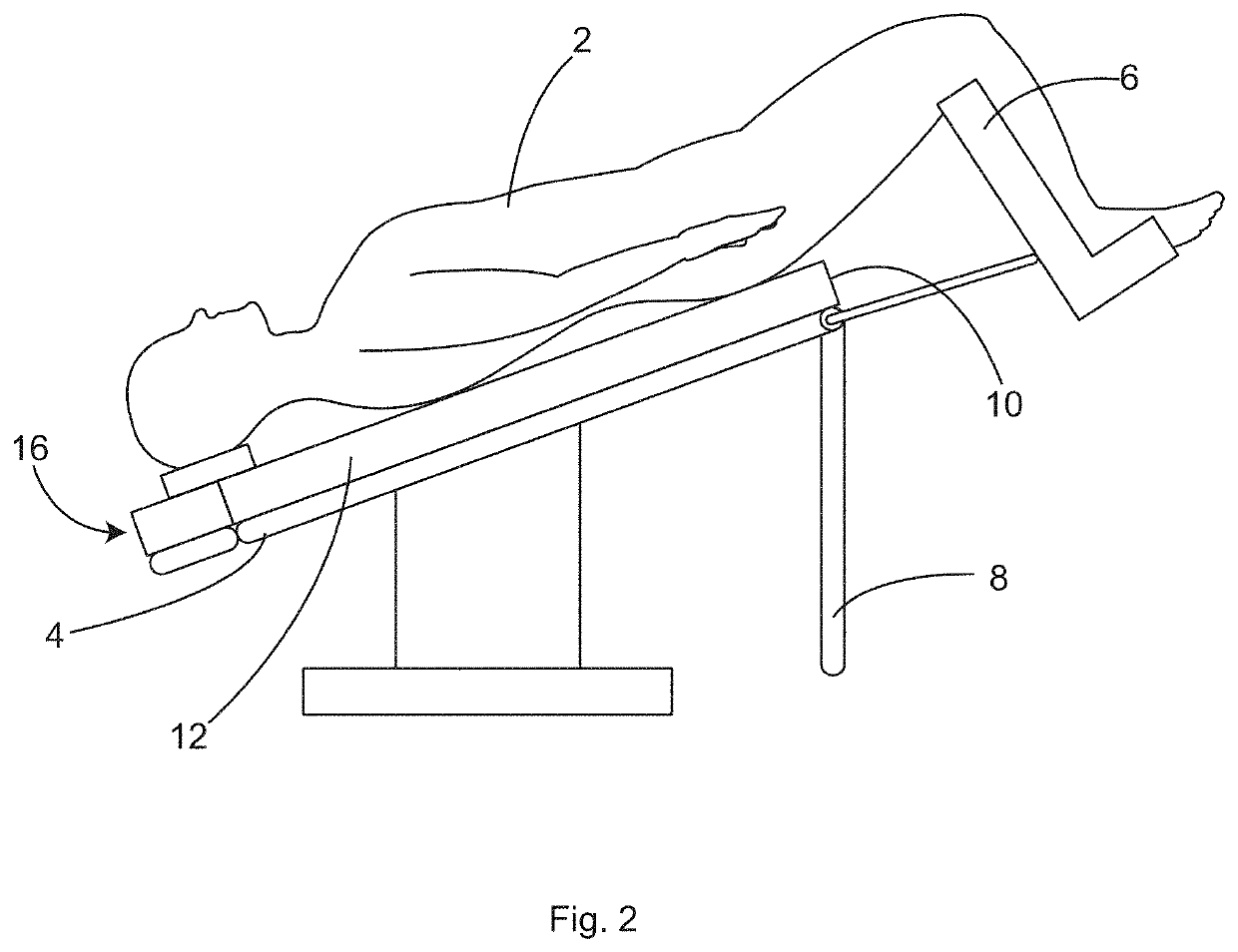
Keeping the patient from sliding off of a surgical table when the table is tilted into a steep, head-down (Trendelenburg) position, is a constant challenge for surgical personnel and a danger for the patient.
This problem has gotten worse in recent years with the advent of laparoscopic surgery and particularly with the advent of robotic surgery.
Depending on the angle or steepness of the head-down Trendelenburg positioning, the patient's weight, and the make-up of the support surface (e.g., bed sheets), patients can be at risk of sliding off of the head end of the surgical table in the Trendelenburg position.
Straps and tape across the chest have proven to not be secure.
Straps over the shoulders have resulted in stretch injuries to the nerves of the brachial plexus.
Similarly, bolsters of foam or bean bags at the patient's shoulders that are secured to the side rails of the bed have also resulted in stretch injuries to the nerves of the brachial plexus and are not recommended by the Association for Operating Room Nurses.
Gel pads are cold and messy because everything sticks to them.
Therefore, unwanted slipping is most likely to occur between the mattress and the foam surgical table overlay.
However, tape sticking to a foam surgical table overlay or straps glued to a foam surgical table overlay as described in U.S. Pat. No. 8,464,720, for example, have a significant risk of becoming unattached when the weight of a 400 pound patient is applied at a 45° head-down angle.
Either the adhesive fails or the top layer of foam pulls away from the foam surgical table overlay while still being adhered to the tape.
In the present disclosure, we refer to the formation of a depression having a depth sufficient to assist in holding a patient on the pad as a “bolster effect.” The disadvantage of any securement device relying wholly or in part on a bolster effect is that bolster-type securement can be overpowered by excessive weight and rounded shaped shoulders that are common with obesity.
Certain conventional arm protection and securing devices are cumbersome, bulky, expensive, and prevent heating of the arms.
The tucked ends of the draw sheet can easily become un-tucked, simply pulling out from under the patient and allowing the arm to fall toward the floor, which may cause nerve injuries.
Robotic surgeries can usually take longer to perform than open surgeries and thus the patients frequently get more hypothermic in the cold operating rooms.
With the patient's arm tucked at their sides, the only skin surface area available for conventional forced-air warming, is the top of the shoulders and the head and thus forced-air warming is ineffective.
As a result, most patients operated in either the Trendelenburg position or the supine position with their arms tucked and warmed with forced-air warming, become very hypothermic.
The same increased risk of hypothermia is experienced by other patients positioned with their arms tucked but not in the Trendelenburg (head down) position.

Method used


Image

  • Patient Securement System for the Surgical Trendelenburg Position
  • Patient Securement System for the Surgical Trendelenburg Position
  • Patient Securement System for the Surgical Trendelenburg Position

Examples


Embodiment Construction

[0059]The following detailed description is exemplary in nature and is not intended to limit the scope, applicability, or configuration of the invention in any way. Rather, the following description provides practical illustrations for implementing various exemplary embodiments. Examples of constructions, materials, dimensions, and manufacturing processes are provided for selected elements, and all other elements employ that which is known to those of skill in the field. Those skilled in the art will recognize that many of the examples provided have suitable alternatives that can be utilized.

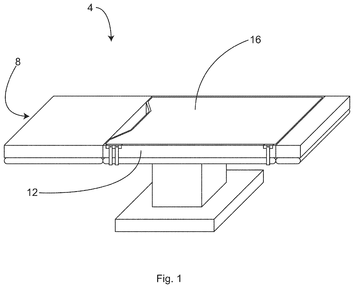
[0060]In some embodiments, as shown in FIG. 1, embodiments include underbody supports such as heated underbody supports, including heated mattresses, heated mattress overlays, and heated pads. The term underbody support may be considered to encompass any surface situated below and supporting a user in a generally recumbent position, such as a patient who may be undergoing surgery, including heat...


PUM

PropertyMeasurementUnit
weightaaaaaaaaaa
thicknessaaaaaaaaaa
diameteraaaaaaaaaa

Abstract

A patient securing overlay is provided that includes a sheet of fabric for supporting a patient's torso on a surgical table. The sheet of fabric has an upper surface configured to face the patient and a lower surface configured to face a surgical table mattress or underbody support. The sheet of fabric includes friction enhancing elements applied to at least a portion of the upper surface thereof. The sheet of fabric can include an extension at a foot end of the sheet of fabric that provides material to be tucked under a foot end of the surgical table mattress or underbody support for securing the foot end of the sheet of fabric to the surgical table mattress or underbody support. The extension can include one or more friction enhancing elements.

Description

CROSS-REFERENCE TO RELATED APPLICATIONS[0001]This application claims priority to U.S. Provisional Patent Application No. 62 / 824,911, filed Mar. 27, 2019, the entire contents of which are incorporated herein by reference.BACKGROUND OF THE INVENTION[0002]Keeping the patient from sliding off of a surgical table when the table is tilted into a steep, head-down (Trendelenburg) position, is a constant challenge for surgical personnel and a danger for the patient. This problem has gotten worse in recent years with the advent of laparoscopic surgery and particularly with the advent of robotic surgery. In both of these instances, the patients are regularly placed into the steep Trendelenburg position so that gravity can move the internal organs out of the way of the laparoscopes. Depending on the angle or steepness of the head-down Trendelenburg positioning, the patient's weight, and the make-up of the support surface (e.g., bed sheets), patients can be at risk of sliding off of the head end...

Claims


Application Information

Patent Timeline
Patent Type & Authority Applications(United States)
IPC IPC(8): A61G13/12A61G13/04B32B5/24B32B7/12B32B3/30
CPCB32B3/30A61G13/1235B32B7/12A61G13/126A61G7/005A61G13/122A61G13/04B32B5/245A61F5/3776A61G13/129A61G7/1026B32B9/007B32B2307/50B32B2255/26B32B2307/732B32B2307/5825B32B27/28B32B2307/302B32B2535/00B32B2262/0253B32B5/32B32B15/046B32B27/32B32B7/04B32B27/40B32B2307/724B32B5/26B32B2307/202B32B9/046B32B5/06B32B27/12B32B27/304B32B7/06B32B2255/10B32B2307/748B32B2266/0235B32B5/024B32B3/08B32B2262/0261B32B5/026B32B2262/106B32B5/18B32B2307/744B32B3/04B32B2266/025B32B2307/204B32B2262/0269B32B5/022B32B3/06B32B5/028B32B21/047B32B2255/02B32B2255/20B32B2255/205B32B3/266B32B2262/0276B32B27/36B32B2307/546B32B2266/0278B32B9/045B32B27/065B32B5/20B32B2307/7265B32B3/02B32B2262/062B32B27/08B32B2305/022A61G2200/32A61G13/101
Inventor AUGUSTINE, SCOTT D.
Owner AUGUSTINE BIOMEDICAL & DESIGN
Learn More