Sole Structure for a Shoe
- Summary
- Abstract
- Description
- Claims
- Application Information
AI Technical Summary
Benefits of technology
Problems solved by technology
Method used
Image


Examples
first embodiment
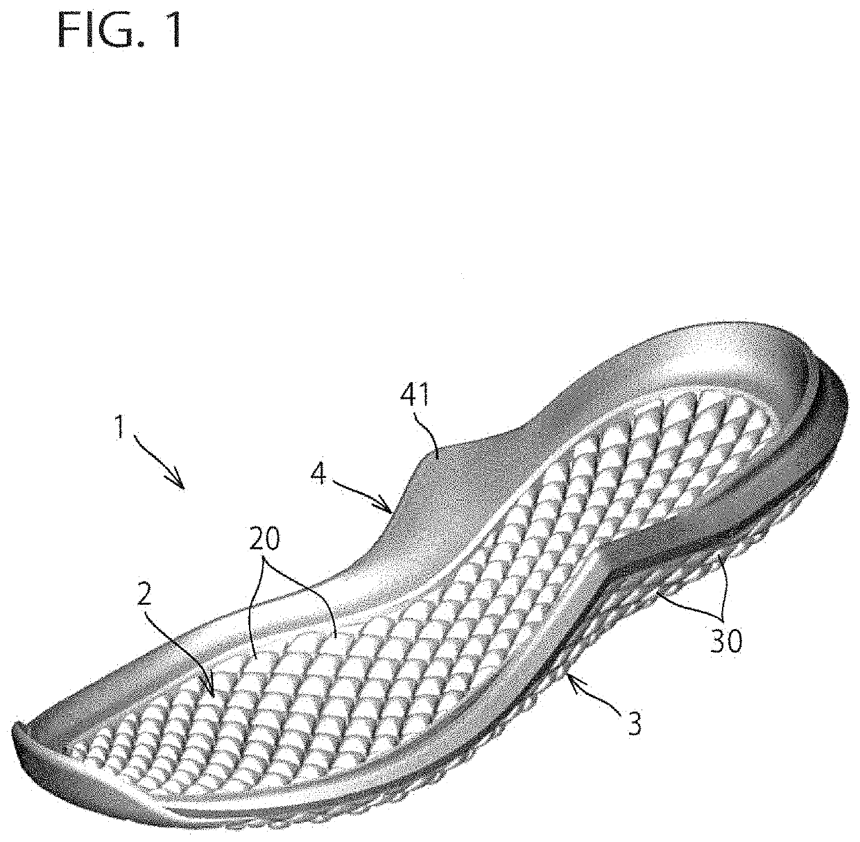
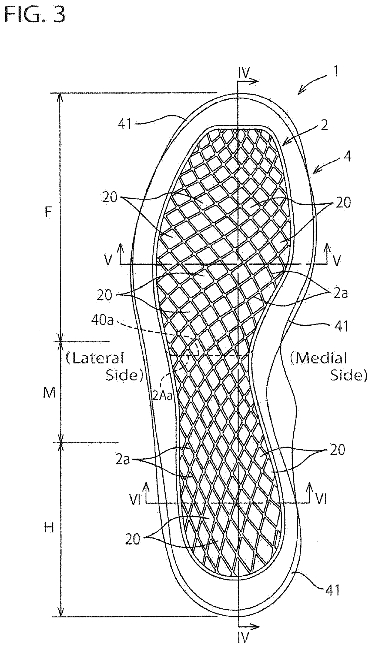
[0058]FIGS. 3 to 7 show a sole structure for a shoe according to the first embodiment of the present invention. As shown in FIGS. 3 to 7, the first midsole 2 and the outsole 3 constituting the sole structure 1 extend from the heel region H through the midfoot region M to the forefoot region F. A large number of first protrusions 20 provided on the upper surface side of the first midsole 2 are spaced apart at a predetermined interval on the upper surface of the first midsole 2 in the longitudinal direction and the width direction. Similarly, a large number of second protrusions 30 provided on the lower surface side of the outsole 3 are spaced apart at a predetermined interval on the lower surface of the first midsole 2 in the longitudinal direction and the width direction. The respective first protrusions 20 are located at positions that correspond vertically to the respective second protrusions 30. Preferably, the first protrusions 20 has a one-to-one correspondence relation relativ...
second embodiment
[0067]FIGS. 8 to 11 show a sole structure for a shoe according to a second embodiment of the present invention. In these drawings, like reference numbers indicate identical or functionally similar elements in the first embodiment. In this second embodiment, the bottom wall surface 40 of the second midsole 4 is disposed at and extends throughout the forefoot region F and the opening 40a of the second midsole 4 is disposed at the rearfoot region.
[0068]In this second embodiment, as with the first embodiment, when the second protrusions 30 of the outsole 3 come into contact with the ground at the time of ground contact, the ground surface information such as the size and direction of the ground reaction force acting from the ground to the second protrusions 30, and angularities of the ground surface or the like are transmitted to the first protrusions 20 of the first midsole 2 disposed at the position corresponding vertically to the second protrusions 30 of the outsole 3, and then trans...
third embodiment
[0072]FIGS. 12 to 15 show a sole structure for a shoe according to a third embodiment of the present invention. In these drawings, like reference numbers indicate identical or functionally similar elements in the first and second embodiments. In this third embodiment, the bottom wall surface 40 of the second midsole 4 is disposed at a region that corresponds to a thenar eminence TE (see FIG. 12) of the foot (or a ball of the foot) and its peripheral region. Also, other regions of the second midsole 4 have an opening 40a formed thereinto. Here, “thenar eminence” designates a first metatarsophalangeal joint (i.e. a metatarsophalangeal joint of a big toe) between a first proximal phalanx and a first metatarsus and the peripheral bulges around the first metatarsophalangeal joint.
[0073]In this third embodiment, as with the first and second embodiments, when the second protrusions 30 of the outsole 3 come into contact with the ground at the time of ground contact, the ground surface infor...
PUM
| Property | Measurement | Unit |
|---|---|---|
| Thickness | aaaaa | aaaaa |
| Structure | aaaaa | aaaaa |
| Stiffness | aaaaa | aaaaa |
Abstract
Description
Claims
Application Information
 - R&D
- Intellectual Property
- Life Sciences
- Materials
- Tech Scout
- Unparalleled Data Quality
- Higher Quality Content
- 60% Fewer Hallucinations
Browse by: Latest US Patents, China's latest patents, Technical Efficacy Thesaurus, Application Domain, Technology Topic, Popular Technical Reports.
© 2025 PatSnap. All rights reserved.Legal|Privacy policy|Modern Slavery Act Transparency Statement|Sitemap|About US| Contact US: help@patsnap.com