Pneumatic tire and method of manufacturing same

A technology for a pneumatic tire and a manufacturing method, applied in the field of pneumatic tires, can solve the problems of insufficient absorption of shock or vibration, deterioration of ride comfort, etc., so as to maintain ride comfort, improve bending rigidity, and restrain rigidity from becoming excessive. high effect

Inactive Publication Date: 2013-11-13
SUMITOMO RUBBER IND LTD
View PDF7 Cites 3 Cited by
  • Summary
  • Abstract
  • Description
  • Claims
  • Application Information

AI Technical Summary

Problems solved by technology

However, if the tread reinforcement layer is added, there is a problem that the rigidity of the entire tread portion tends to become too high, and the impact or vibration from the road surface cannot be sufficiently absorbed, resulting in poor ride comfort.

Method used


Image

  • Pneumatic tire and method of manufacturing same
  • Pneumatic tire and method of manufacturing same
  • Pneumatic tire and method of manufacturing same

Examples


Embodiment

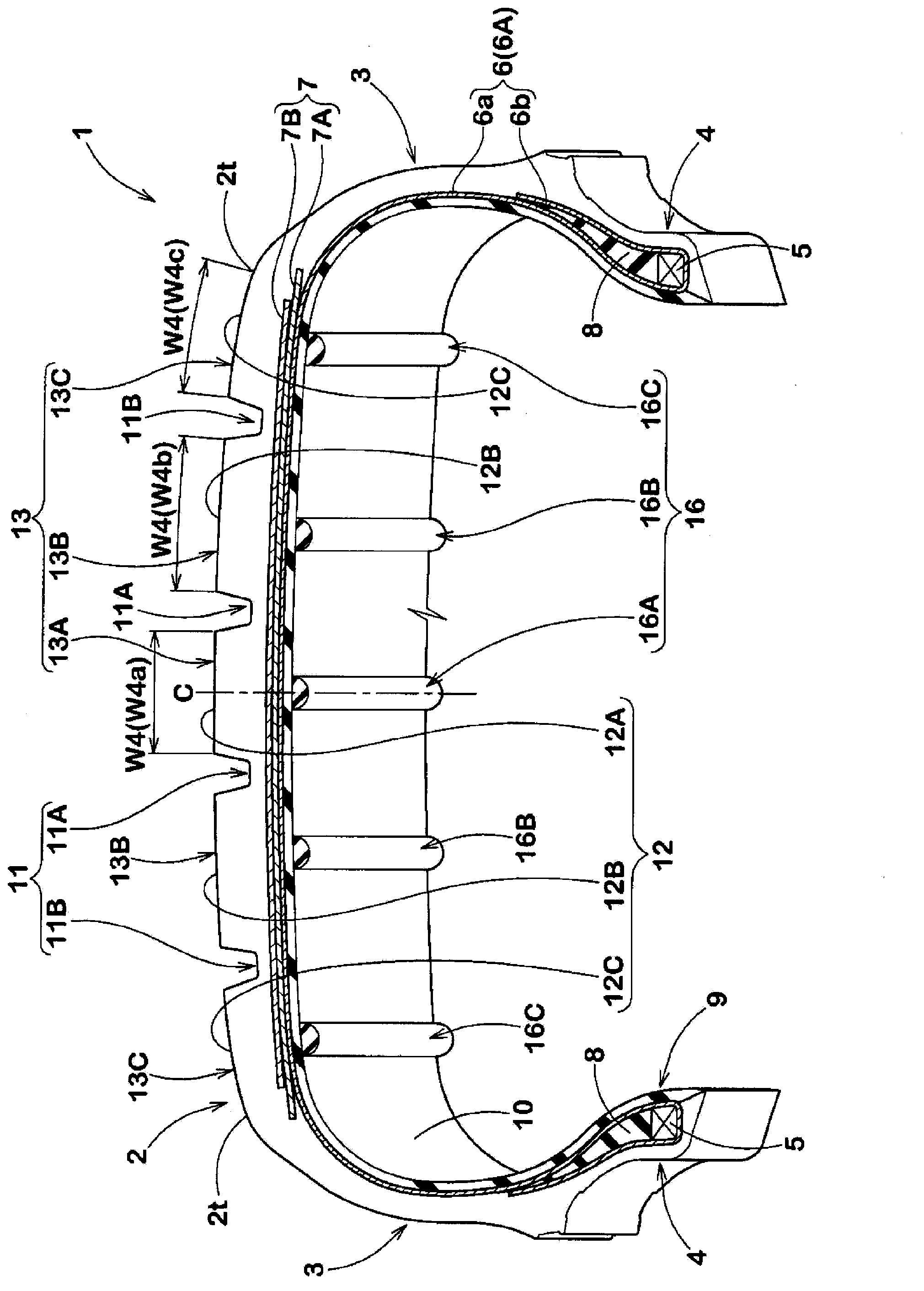
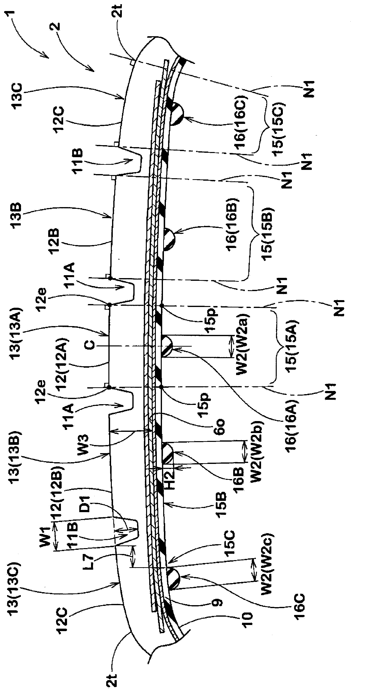
[0090] Manufactured as figure 1 Tires of the basic construction shown and with tread inward ribs and / or main groove inward ribs as shown in Table 1 were evaluated for their performance. In addition, for comparison, the same test was also performed on a tire (Comparative Example 1) that did not have tread inward ribs and main groove inward ribs. Among them, the common specifications are as follows.

[0091] Tire size: 215 / 45R17

[0092] Rim size: 17×7J

[0093] Maximum tread thickness W3: 10mm

[0094] Tread:

[0095] Width W4a of central tread: 20mm

[0096] Width W4b of middle tread: 25mm

[0097] Width W4c of the shoulder tread: 30mm

[0098] Main ditch:

[0099] Maximum width W1: 10mm

[0100] Groove depth D1: 8mm

[0101] The inner area of ​​the main groove:

[0102] Width W7a of the area inside the central main groove: 10mm

[0103] Width W7b of the area inside the shoulder main groove: 8mm

[0104] The test method is as follows.

[0105]

[0106] Each tes...


PUM

PropertyMeasurementUnit
hardnessaaaaaaaaaa
thicknessaaaaaaaaaa

Abstract

The invention provides a pneumatic tire and a method of manufacturing the same, maintaining ride comfort and improving responsibility close to a neutral gear. The pneumatic tire (1) has at least one main groove continuously extending along the tire periphery and treads (12) contacted with a road surface at the outer surface (2S) of a tire surface part (2). The pneumatic tire (1) is provided with tread inward ribs (16) which are protruding toward the inner side in the tire radial direction and extend along the tire periphery at an inner cavity surface (10) of the treads (2) and in tread inner regions (15) of the inner side in the tire radial direction of the treads (12).

Description

technical field [0001] The present invention relates to a pneumatic tire capable of improving responsiveness near neutral while maintaining riding comfort, and a method for manufacturing the same. Background technique [0002] Pneumatic tires are known that include, for example, at least one main groove continuously extending in the tire circumferential direction and a tread that contacts a road surface on the outer surface of a tread portion (for example, refer to Patent Document 1). [0003] Since the above-mentioned tread directly contacts the road surface, it is desirable to sufficiently increase the rigidity in the tire circumferential direction of the land portion on which the tread is formed. In particular, in order to improve the response performance near neutral where the slip angle is small at the start of turning, it is preferable to increase the bending rigidity in the tire circumferential direction of such a land portion. [0004] Patent Document 1: Japanese Pa...

Claims


Application Information

Patent Timeline
Patent Type & Authority Applications(China)
IPC IPC(8): B60C19/00B29D30/12
Inventor 两角顺一郎
Owner SUMITOMO RUBBER IND LTD
Why Eureka
Try Eureka