
Optically isotropic liquid crystal composition and optical switching device using same

a liquid crystal composition and optical switching technology, applied in liquid crystal compositions, instruments, chemistry apparatuses and processes, etc., can solve the problems of device limited control time, poor durability, and difficulty in controlling steering angle, and achieve and the effect of easy development of high transparency and isotropy

Inactive Publication Date: 2020-09-24
JNC CORP +1
View PDF0 Cites 1 Cited by
  • Summary
  • Abstract
  • Description
  • Claims
  • Application Information

AI Technical Summary

Benefits of technology

The patent describes a mixture of a polymerizable monomer and a liquid crystal composition that can be used to create a polymer / liquid crystal composite material with high transparency and isotropy. The mixture can contain a polymerization initiator, a curing agent, a curing promoter, a stabilizer, a dichroic dye, a photochromic compound, and other additives. The polymerization temperature should be set to a level where the mixture develops the isotropic phase. The raw material monomer of the polymer can be a monomer, macromonomer, or oligomer with low molecular weight, and a monomer with a mesogen site can be used to further improve the properties of the composite material.

Problems solved by technology

A mechanical device such as micro electro mechanical systems (MEMS) is studied for polarized light control, but has many issues such as difficulty in controlling a steering angle and poor durability because a movable part is of the mechanical system.
In the device using the liquid crystal medium for polarized light control application, a nematic liquid crystal medium is used, but a response time is long, and therefore the device has an issue of the limited number of times of control per fixed time.
As described above, in a mechanical device studied for polarized light control application, issues of difficulty in controlling a steering angle and poor durability and so forth have remained.
Moreover, in a device using a nematic liquid crystal medium, a response time is long, whereby the number of controls per fixed time has been limited.

Method used


Image

  • Optically isotropic liquid crystal composition and optical switching device using same
  • Optically isotropic liquid crystal composition and optical switching device using same
  • Optically isotropic liquid crystal composition and optical switching device using same

Examples


example 1

[0137]Liquid crystal composition NLC-A was prepared by mixing liquid crystal compounds shown in a diagram below at a proportion below.

Liquid Crystal Composition NLC-A

[0138]

5-HBB(F)B-2(1) 10%3-GB(F)B(F,F)XB(F,F)-F(2)11.7%4-GB(F)B(F,F)XB(F,F)-F(2)10.8%5-GB(F)B(F,F)XB(F,F)-F(2)10.8%2-GB(F,F)XB(F)B(F,F)-F(2)16.2%3-GB(F,F)XB(F)B(F,F)-F(2)16.2%4-B(F)B(F,F)B(F,F)XB(F,F)-F(3) 6.3%5-B(F)B(F,F)B(F,F)XB(F,F)-F(3) 6.3%6-B(F)B(F,F)B(F,F)XB(F,F)-F(3) 6.3%3-B(F)B(F,F)B(F,F)XB(F,F)-CF3(3) 2.7%4-B(F)B(F,F)B(F,F)XB(F,F)-CF3(3) 2.7%

[0139]A maximum temperature (° C.) of liquid crystal composition NLC-A was 112.8 to 117.0.

[0140]Next, liquid crystal composition CLC-A composed of liquid crystal composition NLC-A (95.0% by weight) and chiral agent (8H)BN−H5 (5.0% by weight) was obtained.

[0141]A phase transition temperature (° C.) of liquid crystal composition CLC-A was N*103.4 to 104.7 BP−BP+I−I.

[0142]A chemical structural formula of chiral agent (8H)BN−H5 is as described below.

Preparation of a Mixture (ML...

example 2

[0147]Liquid crystal composition NLC-B was prepared by mixing liquid crystal compounds shown in a diagram below at a proportion below.

Liquid Crystal Composition NLC-B

[0148]

5-HBB(F)B-2(1)14% 3-GB(F)B(F,F)XB(F,F)-F(2)4%4-GB(F)B(F,F)XB(F,F)-F(2)4%5-GB(F)B(F,F)XB(F,F)-F(2)4%1-GB(F,F)XB(F)B(F,F)-F(2)5%2-GB(F,F)XB(F)B(F,F)-F(2)18% 3-GB(F,F)XB(F)B(F,F)-F(2)18% 4-GB(F,F)XB(F)B(F,F)-F(2)12% 4-B(F)B(F,F)B(F,F)XB(F,F)-F(3)2%5-B(F)B(F,F)B(F,F)XB(F,F)-F(3)2%6-B(F)B(F,F)B(F,F)XB(F,F)-F(3)2%3-B(F)B(F,F)B(F,F)XB(F,F)-CF3(3)2.5% 4-B(F)B(F,F)B(F,F)XB(F,F)-CF3(3)2.5% 5-B(F)B(F,F)B(F,F)XB(F,F)-CF3(3)2.5% 6-B(F)B(F,F)B(F,F)XB(F,F)-CF3(3)2.5% H-BOB-F(4)5%

[0149]A maximum temperature (° C.) of liquid crystal composition NLC-B was 84.2 to 87.5.

[0150]Next, liquid crystal composition CLC-B composed of liquid crystal composition NLC-B (95.0% by weight) and chiral agent (8H)BN-H5 (5.0% by weight) was obtained.

[0151]A phase transition temperature (° C.) of liquid crystal composition CLC-B was N*77.8 to 79.1 BP−B...

example 3

[0156]Liquid crystal composition NLC-C was prepared by mixing liquid crystal compounds shown in a diagram below at a proportion below.

Liquid Crystal Composition NLC-C

[0157]

5-HBB(F)B-2(1)17% 3-GB(F)B(F,F)XB(F,F)-F(2)3%4-GB(F)B(F,F)XB(F,F)-F(2)3%5-GB(F)B(F,F)XB(F,F)-F(2)3%1-GB(F,F)XB(F)B(F,F)-F(2)8%2-GB(F,F)XB(F)B(F,F)-F(2)18% 3-GB(F,F)XB(F)B(F,F)-F(2)18% 4-B(F)B(F,F)B(F,F)XB(F,F)-F(3)2%5-B(F)B(F,F)B(F,F)XB(F,F)-F(3)2%6-B(F)B(F,F)B(F,F)XB(F,F)-F(3)2%3-B(F)B(F,F)B(F,F)XB(F,F)-CF3(3)2.5% 4-B(F)B(F,F)B(F,F)XB(F,F)-CF3(3)2.5% 5-B(F)B(F,F)B(F,F)XB(F,F)-CF3(3)2.5% 6-B(F)B(F,F)B(F,F)XB(F,F)-CF3(3)2.5% 2-HH-3(4)5%H-BOB-F(4)4%3-BB(F)B(F,F)-F(4)5%

[0158]A maximum temperature (° C.) of liquid crystal composition NLC-C was 90.3 to 102.9.

[0159]Next, liquid crystal composition CLC-C composed of liquid crystal composition NLC-C (95.0% by weight) and chiral agent (8H)BN-H5 (5.0% by weight) was obtained. A phase transition temperature (° C.) of liquid crystal composition CLC-C was N* 81.5 to 82.2 BP−BP...


PUM

PropertyMeasurementUnit
Percent by massaaaaaaaaaa

Abstract

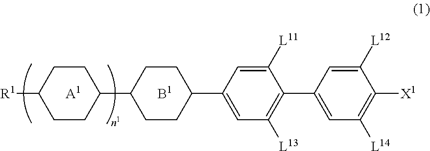
A device using a liquid crystal medium exhibiting an optically isotropic liquid crystal phase, particularly, a blue phase liquid crystal medium for polarized light control application, in which reduction of an effective dielectric constant in a high frequency region is suppressed. A liquid crystal composition contains achiral component T, and has a liquid crystal phase optically exhibiting isotropy, in which achiral component T contains at least one compound selected from the group of compounds represented by formula (1) as a first component, at least one compound selected from the group of compounds represented by formula (2) and formula (3) as a second component, and is used for optical switching for controlling retardation by electric field-induced birefringence.

Description

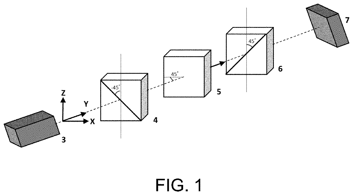
CROSS-REFERENCE TO RELATED APPLICATION[0001]This application claims the priority benefit of Japan application no. 2019-053130, filed on Mar. 20, 2019 and Japan application no. 2020-000674, filed on Jan. 7, 2020. The entirety of each of the above-mentioned patent applications is hereby incorporated by reference herein and made a part of this specification.BACKGROUNDTechnical Field[0002]The disclosure relates to a liquid crystal medium (a liquid crystal composition, a polymer / liquid crystal composite material and so forth) exhibiting an optically isotropic liquid crystal phase to be used in an optical switching device, for example, a laser imaging detection and ranging (LIDAR), a mixture of a polymerizable monomer or the like and the liquid crystal composition, and a device using the same.Background Art[0003]An optical switching device is a device that switches or turns on / off an optical path, and a system thereof includes a mechanical system, an electronic system, an all-optical syst...

Claims


Application Information

Patent Timeline
IPC IPC(8): C09K19/34C09K19/58C09K19/56C09K19/02G02F1/1334
CPCC09K2019/3422G02F2203/11G02F1/1334C09K19/3402C09K19/0216G02F2203/13C09K19/586C09K19/56C09K19/0275C09K19/44C09K19/542G01S7/481G02F1/137G02F1/139C09K19/10C09K2019/0448C09K2019/0466C09K2019/124C09K2019/3004C09K2019/3019C09K2019/3025G02F1/13793
Inventor OKABE, EIJITOBATA, HITOSHI
Owner JNC CORP
Learn More