Actuator for seat adjustment devices
- Summary
- Abstract
- Description
- Claims
- Application Information
AI Technical Summary
Benefits of technology
Problems solved by technology
Method used
Image

Examples
first embodiment
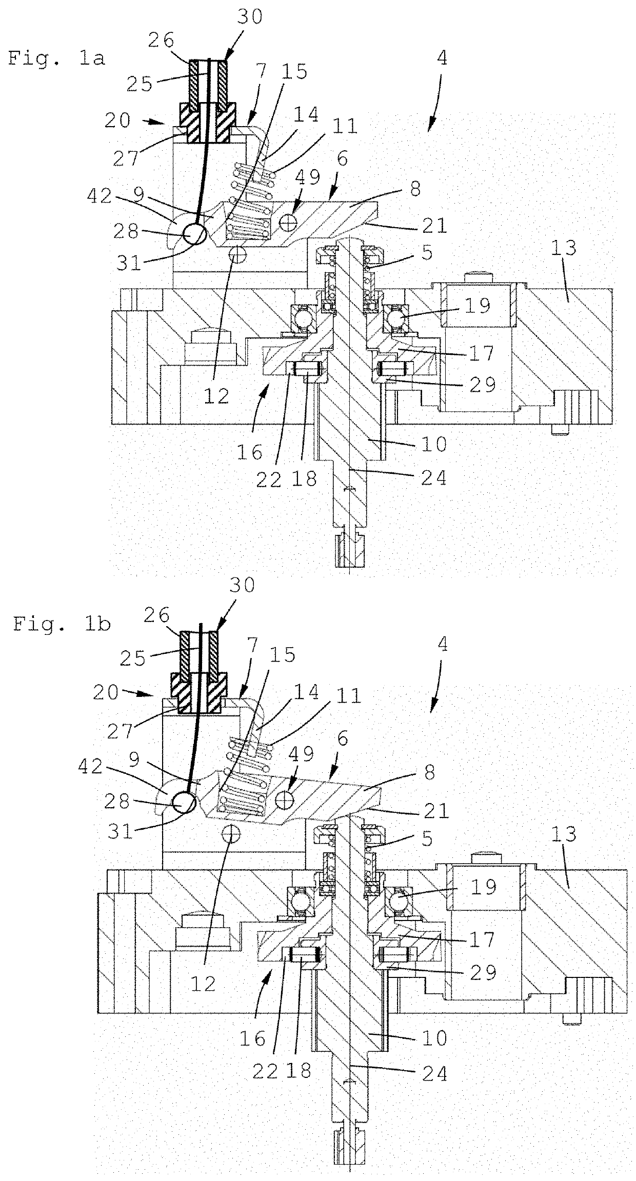
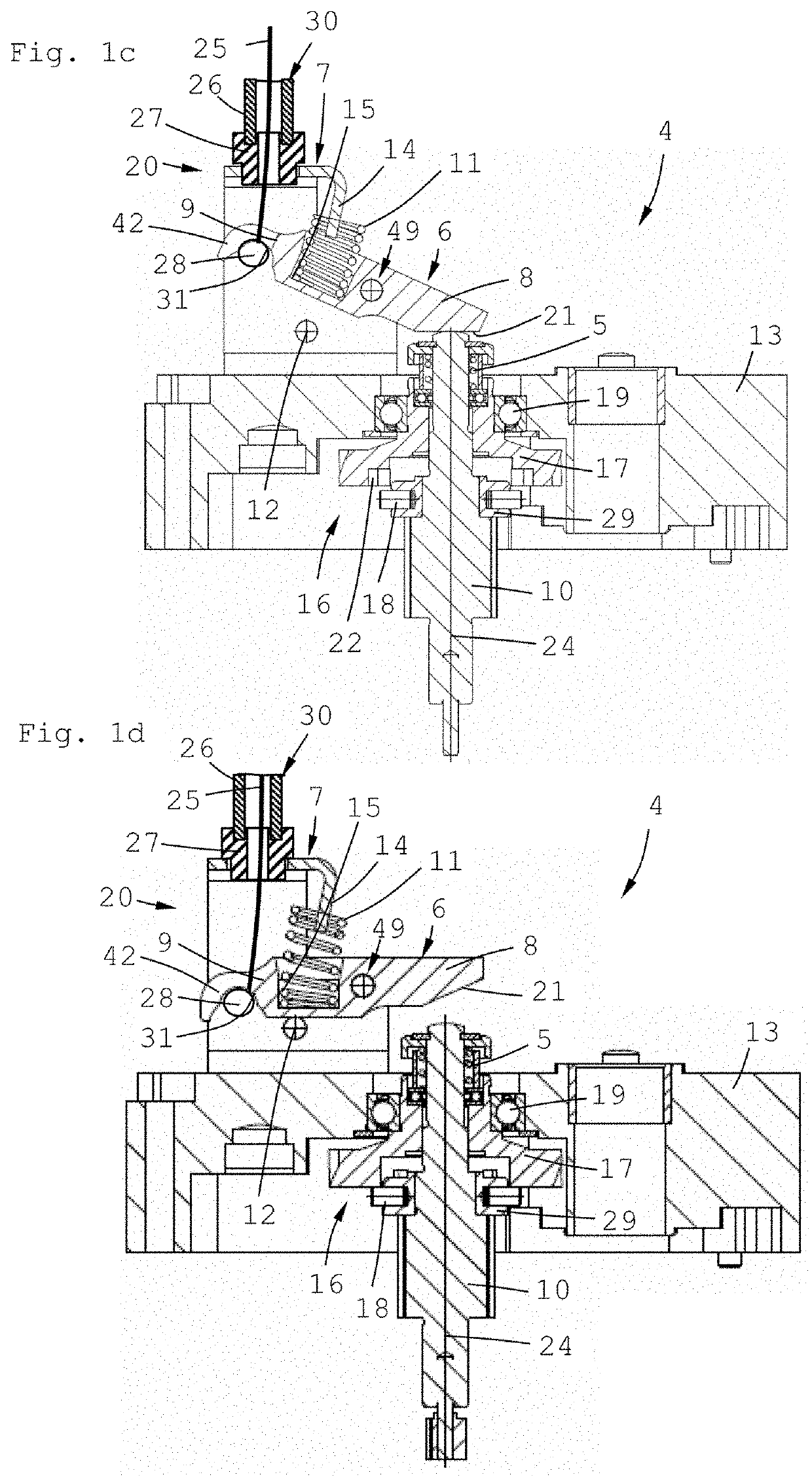
[0038]FIG. 1a, FIG. 1b, FIG. 1c and FIG. 1d show a coupling device 4 of an actuating drive in four different positions, with a housing 13, a coupling means 10 rotatably mounted about a coupling axis 24 in the housing 13 by a ball bearing 19, a coupling disc 17 and a Bowden cable 30. The coupling disc 17 is in geared engagement with a final gear stage (not shown here). The coupling means 10 is in geared connection with an electric motor via a plurality of gear stages and a friction brake.
[0039]The coupling means 10 carries a pressed-on ring 29 with radially pressed-in coupling pins 18 which engage positively in corresponding recesses 22 of the coupling disc 17. A coupling engagement spring 5 ensures stable positive locking between the coupling pins 18 and the recesses 22 during motorized operation.
[0040]The Bowden cable 30 has a bearing block 7 mounted on the housing 13, a coupling lever 6, a return spring 11, a pull cable 25, a sleeve 26 and a bushing 27. The Bowden cable 30 is rout...
second embodiment
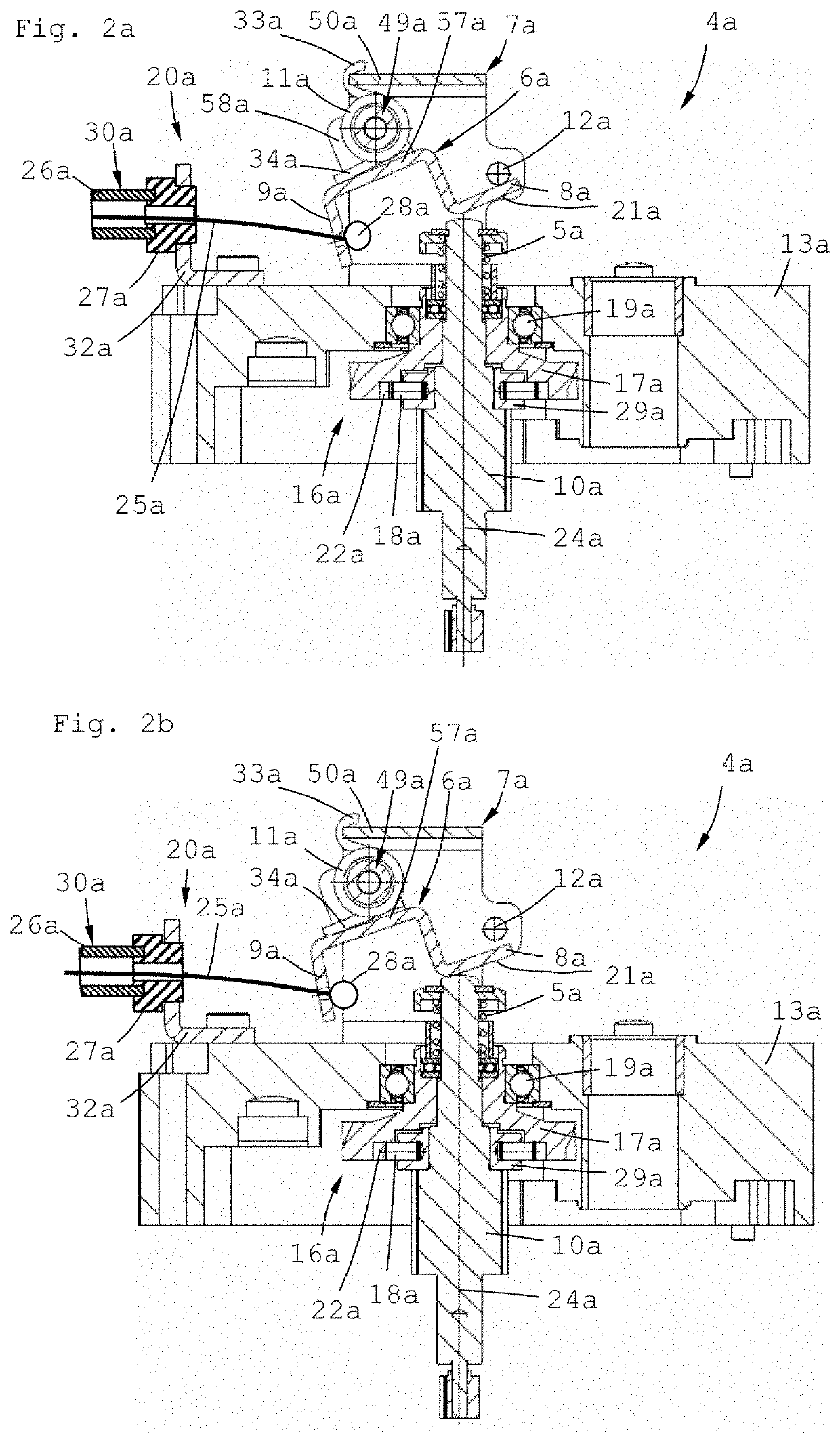
[0047]FIG. 2a, FIG. 2b, FIG. 2c and FIG. 2d show a coupling device 4 of an actuating drive in four different positions, with a housing 13a, a coupling means 10a rotatably mounted about a coupling axis 24a in the housing 13a by a ball bearing 19a, a coupling disc 17a and a Bowden cable 30a. The coupling disc 17a is in geared engagement with a final gear stage (not shown here). The coupling means 10a is in geared connection with an electric motor via a plurality of gear stages (not shown here).
[0048]The coupling means 10a carries a pressed-on ring 29a with radially pressed-in coupling pins 18a which engage positively in corresponding recesses 22a of the coupling disc 17a. A coupling engagement spring 5a ensures stable positive locking between the coupling pins 18a and the recesses 22a during motorized operation.
[0049]The Bowden cable 30a has a bearing block 7a mounted on the housing 13a, a coupling lever 6a, a return spring 11a, a pull cable 25a, a sleeve 26a and a bushing 27a. The co...
third embodiment
[0055]FIG. 3a shows an exploded view of a coupling device of an actuating drive, with a bearing block 7b, a coupling lever 6b, a return spring 11b in the form of a compression spring, a pivot pin 53b and a stop 12b. Pivot pin receivers 55b and stop pin receivers 56b are provided in the bearing block 7b for receiving the pivot pin 53b and the stop 12b. Pivot pin through-holes 23b for receiving the pivot pin 53b are formed in the pivot lever 6b. In FIG. 3a the pivot pin and the stop 12b are shown with press-fit stemmed ends; however, during assembly at least the press-fit stemming 59b at one end is produced only after these components have been assembled in the bearing block 7a. The bearing block 7b has an L-shaped, angled projection 14b which is provided with two notches 35b. These serve as support points for the return spring 11b. Fastened in the coupling lever 6a is a receiving pin 36b (riveted here) which represents a guide for the return spring 11b. For ease of assembly, the rece...
PUM
 Abstract
Description
Claims
Application Information
 - R&D
- Intellectual Property
- Life Sciences
- Materials
- Tech Scout
- Unparalleled Data Quality
- Higher Quality Content
- 60% Fewer Hallucinations
Browse by: Latest US Patents, China's latest patents, Technical Efficacy Thesaurus, Application Domain, Technology Topic, Popular Technical Reports.
© 2025 PatSnap. All rights reserved.Legal|Privacy policy|Modern Slavery Act Transparency Statement|Sitemap|About US| Contact US: help@patsnap.com