Solid body joining of a carrier body and a cover layer, particularly by anodic bonding

Active Publication Date: 2015-05-21
ASML NETHERLANDS BV
View PDF5 Cites 0 Cited by
  • Summary
  • Abstract
  • Description
  • Claims
  • Application Information

AI Technical Summary

Benefits of technology

The invention is a method of joining a cover layer to a carrier body, which solves the problems of conventional techniques. A gap-free mechanical material contact is created between the surfaces of the cover layer and carrier body, resulting in a laminar, gap-free connection. No locally restricted pressing force is exerted, avoiding a moving bonding front. The cover layer can also be mechanically processed to adjust its form and remove any possible traces of the action of the pressing force. The technical effect is a more stable and reliable bond between the cover layer and carrier body.

Problems solved by technology

With conventional joining processes, in particular with conventional anodic bonding, this has not been possible since the process conditions of these methods were limited to the joining of planar surface.

Method used


Image

  • Solid body joining of a carrier body and a cover layer, particularly by anodic bonding
  • Solid body joining of a carrier body and a cover layer, particularly by anodic bonding
  • Solid body joining of a carrier body and a cover layer, particularly by anodic bonding

Examples


Embodiment Construction

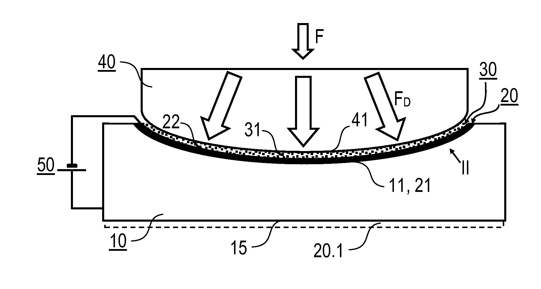
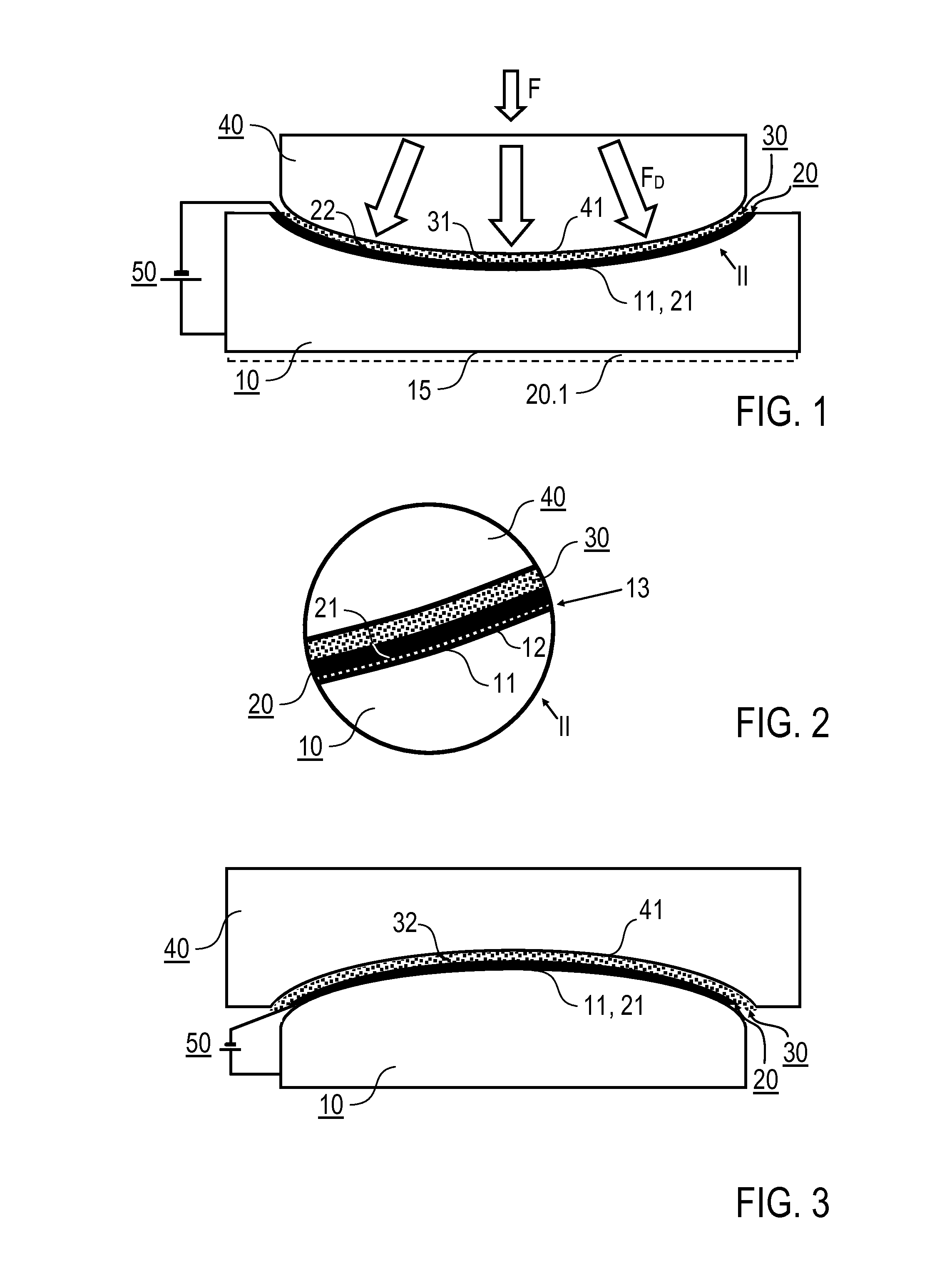
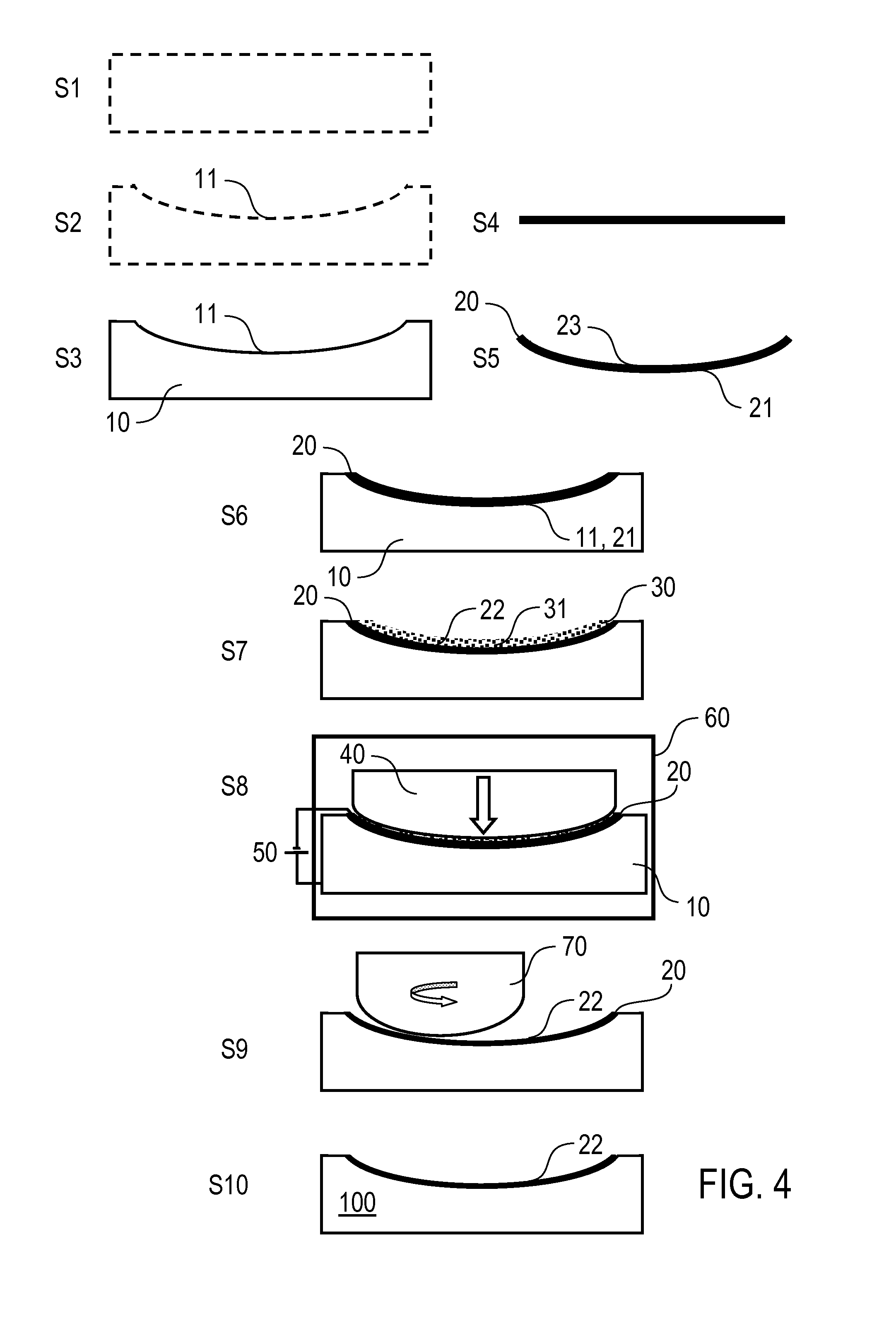
[0035]Reference is made below to variants of the invention wherein a cover layer is bonded by anodic bonding to a curved carrier body. It should be noted that the invention is usable accordingly for the bonding of a cover layer to a carrier body with other solid body joining methods, for example, diffusion welding or soldering. Furthermore, reference is made to the solid body joining of a ceramic carrier body with a glass cover layer. However, the implementation of the invention is not restricted to these materials, but rather is possible with other material combinations which are suitable as bonding partners for solid body joining, for example, glass-ceramic-metal soldering, diffusion welding or nanostructured bonding. Details of anodic joining are not given below insofar as they are per se known from the prior art. Bonding parameters can be selected depending on the concrete application of the invention wherein anodic bonding can preferably take place at a raised temperature, for ...


PUM

PropertyMeasurementUnit
Forceaaaaaaaaaa
Pressureaaaaaaaaaa
Flow rateaaaaaaaaaa

Abstract

In a method for solid body joining of a carrier body (10) and a cover layer (20), in particular by anodic bonding, the cover layer (20) is pressed with a pressing force against a curved carrier body surface (11), wherein the pressing force during the solid body joining is distributed by way of a pressure intermediary device (30) areally and simultaneously over the whole cover layer (20) and is directed perpendicularly to the curvature of the carrier body surface (11). A composite component comprising a carrier body (10) and a cover layer (20) is also disclosed, wherein a curved areal joining region (13) is formed between a cover layer surface (21) and a carrier body surface (11).

Description

BACKGROUND[0001]The invention relates to a method for solid body joining of a carrier body and a cover layer, in particular a method for anodic bonding, wherein the carrier body and the cover layer are connected areally. The invention further relates to a composite component comprising a carrier body and a cover layer, in particular an optical component, for example, a mirror. Applications of the invention are to be found in the manufacturing of composite components, particularly optical components, for example, mirrors for the purposes of optical imaging.[0002]Anodic bonding is a generally known joining process for connecting planar surfaces of, for example, micromechanical components, semiconductor wafers or optical components. By way of example, in DE 10 2009 011 863, an optical mirror comprising a ceramic carrier body with a planar surface and a glass cover layer is disclosed, wherein the glass cover layer is connected by anodic bonding to the surface of the ceramic carrier body...

Claims


Application Information

Patent Timeline
IPC IPC(8): G02B5/10B32B17/06B32B38/10B32B18/00B32B37/10B32B38/00
CPCG02B5/10B32B37/10B32B38/0012B32B17/06B32B38/10B32B18/00B32B38/0008B32B38/1866B32B2309/02B32B2315/02B32B2551/00C04B2237/70C04B37/042C04B37/045C04B2237/062C04B2237/365C04B2237/52C04B2237/54C04B2237/76C04B2237/84Y10T428/24521Y10T156/10Y10T156/1028C03C27/00B32B17/00
Inventor PAMPUCH, CARSTENHALALO, KHALDOUNSCHMIDT, VOLKER
Owner ASML NETHERLANDS BV
Why Eureka
Try Eureka