Mounting device for plumbing or electrical equipment

Active Publication Date: 2016-06-02
BRISTAN GROUP
View PDF22 Cites 2 Cited by
  • Summary
  • Abstract
  • Description
  • Claims
  • Application Information

AI Technical Summary

Benefits of technology

[0050]This improves the general flexibility of the mounting device and adaptor arrangement to various installation situations, with media being delivered to the equipment at a range of locations relative to the mounting device. The adaptor may be rotatable about the connection axis of the connector, between first and second configurations, in order to connect the media at first and second locations relative to the mounting device. This helps to facilitate the adaptation o

Problems solved by technology

Further, one of the most time-consuming aspects of an installation process can be accurately measuring up locations for fixing holes to be formed and ensuring that the holes are appropriately formed at the desired locations, as defined by a set of fixed mounting points on the equipment to be mounted.
Even when care is tak

Method used


Image

  • Mounting device for plumbing or electrical equipment
  • Mounting device for plumbing or electrical equipment
  • Mounting device for plumbing or electrical equipment

Examples


Example

DETAILED DESCRIPTION OF THE DRAWINGS

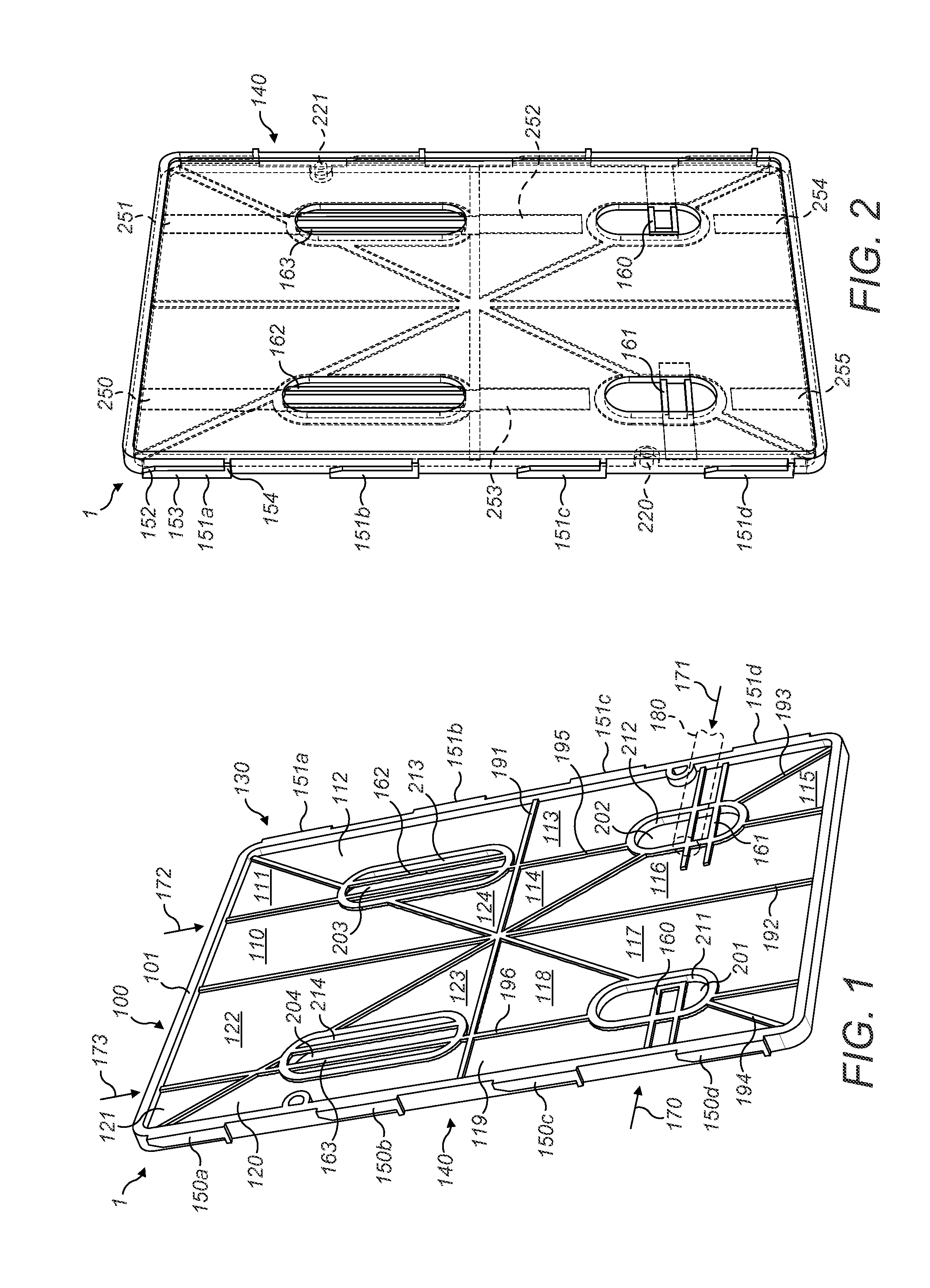
[0087]FIG. 1 shows a mounting device according to the present invention. The device comprises a substantially planar body 100. The planar body comprises a fixing region 110. This fixing region 110 may be divided into a plurality of fixing regions separately numbered 110 to 124 in the Figure. In the example shown, the fixing regions are made from a transparent material. Making the fixing regions from a transparent material allows a user to look through the fixing regions and to see the surface to which the mounting plate is going to be attached through the fixing regions. In practice, this means that the mounting device 1 can be used to mount equipment to a surface, by using fixing points which are pre-formed in the surface at locations corresponding to substantially any point within the fixing regions 110 to 124.

[0088]The device comprises a front, or equipment-facing, face 130, which can be seen in full in FIG. 1. The device also comprises a rear,...


PUM


Abstract

A mounting device for mounting plumbing or electrical equipment to a surface is disclosed. The device has a substantially planar body, comprising an engagement arrangement, for engagement with the equipment to be mounted to the mounting device; an opening for allowing passage of an electrical wire and/or a pipe through the plane of the body; alignment means arranged to allow a user to identify a correct location of the opening relative to pipework or cabling fixed to, or protruding from, the surface; and a substantially visually transparent fixing region configured to allow a user to identify a fixing point on the surface while looking through the fixing region, and to locate fixing means in the surface at the fixing point, through the fixing region, to fix the mounting device to the surface.

Description

CROSS-REFERENCE TO RELATED APPLICATION[0001]This application claims priority to United Kingdom Patent Application No. GB1421318.5, filed on Dec. 1, 2014, the disclosure of which is expressly incorporated by reference herein.TECHNICAL FIELD[0002]The present invention relates to a mount for attaching an item of plumbing or electrical equipment to a surface, more particularly to a generally planar wall or ceiling. More particularly, the invention relates to a mounting device which is arranged to permit a user to re-use pre-formed mounting holes to mount plumbing equipment to a surface, and a related method.BACKGROUND TO THE INVENTION[0003]It is often desirable to mount an item of plumbing or electrical equipment to a surface. Most commonly, particularly in domestic settings, it is desirable to mount plumbing or electrical equipment to fixed surface such as a wall, or in some cases to a floor or ceiling. In most instances, the installation procedure will involve forming holes in a surfa...

Claims


Application Information

Patent Timeline
IPC IPC(8): H02G3/00F16M13/02
CPCF16M13/02H02G3/263
Inventor MACKERETH, PAUL JAMESMCGOWAN, LUKEPELAYO, XORGE CASTROCURTIS, STUARTSTRUTT, BENJAMIN JOHN
Owner BRISTAN GROUP
Why Eureka
Try Eureka