Apparatus for manufacturing electrical energy storage devices

Active Publication Date: 2020-07-09
MANZ ITAL
View PDF0 Cites 0 Cited by
  • Summary
  • Abstract
  • Description
  • Claims
  • Application Information

AI Technical Summary

Benefits of technology

The invention is about an apparatus for machining material that can change in size, specifically for making electrical energy storage devices. The apparatus has multiple machining stations that are adaptable to the size of the product being made. One advantage is that the distance between the stations can be reduced, resulting in a shorter path for the material to traverse the stations, which saves time and space. Another advantage is that the apparatus can adapt to changes in the machining steps, which makes it easier to produce different versions of the product.

Problems solved by technology

One of the problems of the prior art is to adapt the apparatus to a change in product size, as in general the size change (in particular the length dimension of the electrodes) can cause a variation of the machining step and thus of the step of intermittent feed of the material, with the consequent need to compensate in some way for this variation so that, during each stop of the material, the machine can be performed substantially simultaneously in all the machining stations.
Firstly, there is the need to set up a relatively long path of material and, in general, a large longitudinal dimension of the apparatus.
Secondly, the arrangement of path portions of variable length involves various variations in the advancing direction of the material, increasing the risk of great tension and veering of the material, moreover, the great length of the path of the material entails an increase in the mass of the moving material, so in general material cannot be used that is too fragile and / or thin.
Further, the apparatus of known type has a certain constructional complication that is due, in particular, to the complexity of the feed path and of the corresponding adjusting system, with a resulting increased risk of machining imprecision and defects in the finished product (electrical energy storage device).

Method used


Image

  • Apparatus for manufacturing electrical energy storage devices
  • Apparatus for manufacturing electrical energy storage devices
  • Apparatus for manufacturing electrical energy storage devices

Examples


Embodiment Construction

[0029]With reference to the aforementioned figures, for the sake of greater clarity of expression, similar elements have been indicated by the same numbering even if they belong to different embodiments.

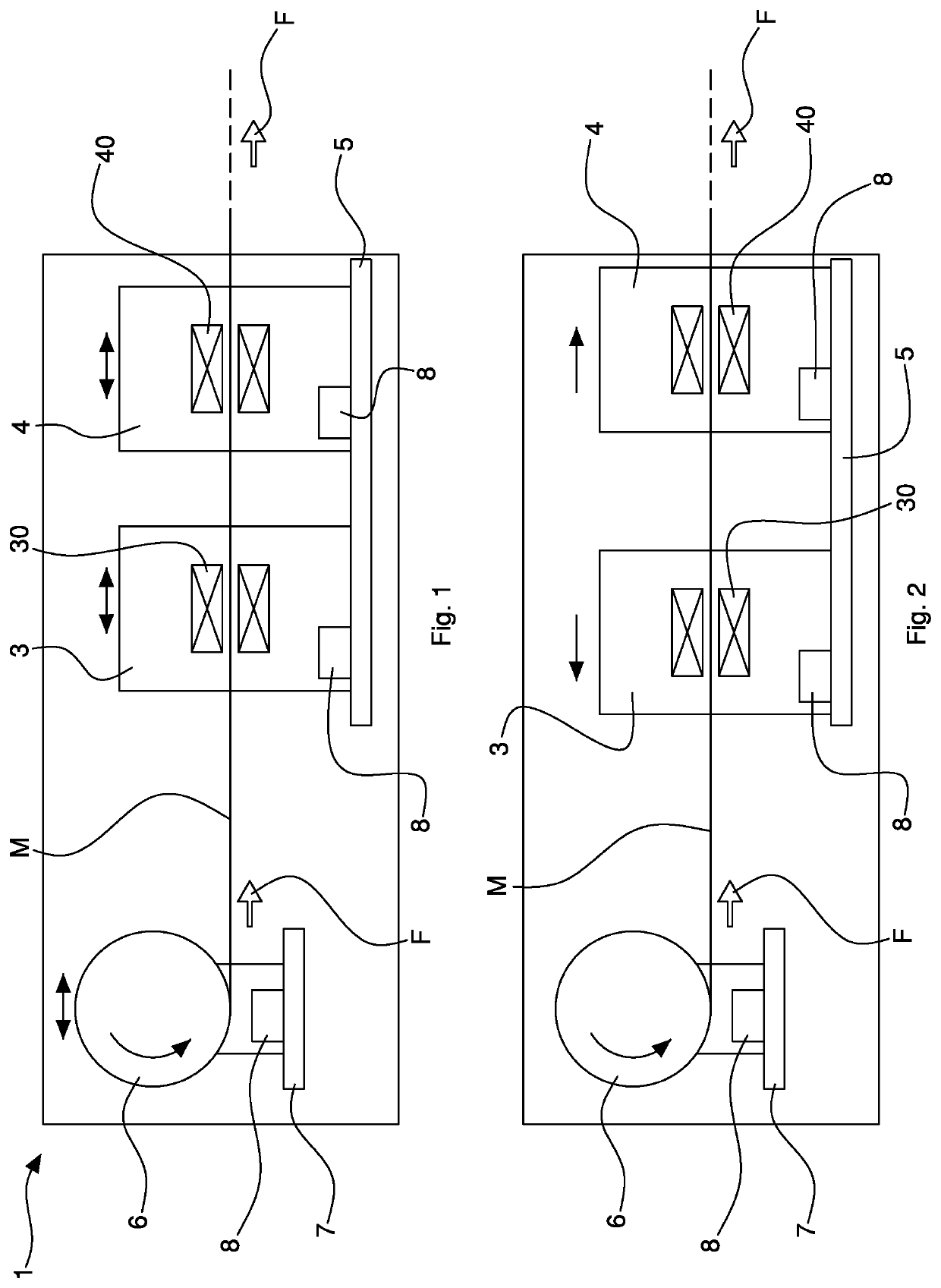
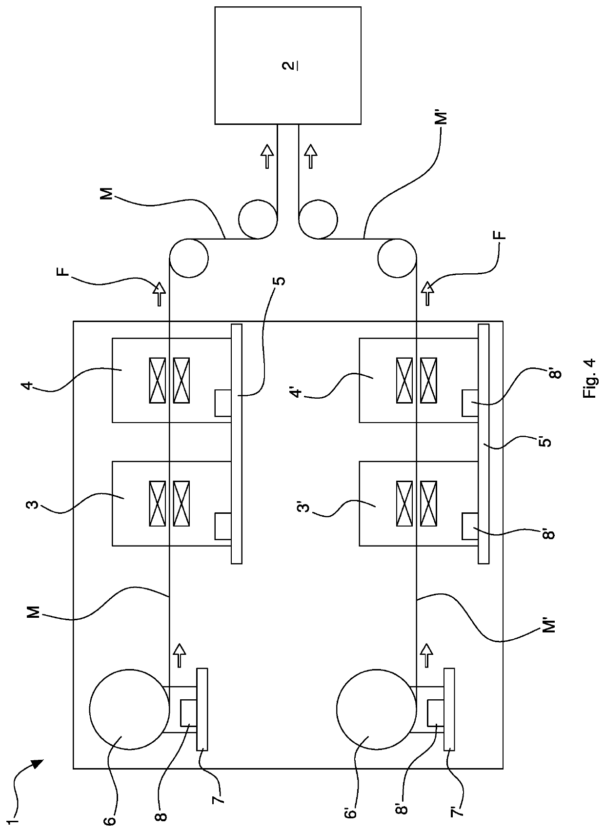
[0030]With 1 overall a machining apparatus has been indicated, in particular for machining material / s M in the form of a web, strip, sheet, etc. The machining apparatus 1 may be used, in particular, to produce an electrical energy storage device, for example to machine material M comprising an electrode tape (cathode and / or anode) and / or at least one separator. The material M may comprise continuous material intended to be wound around a core rotating in a winding device 2 for forming an electrical energy storage device, or intended to be singled out and then stacked to form an electrical energy storage device.

[0031]The machining apparatus 1 may comprise, in particular, a feed path of the material M. The feed path may comprise, in particular, means (for example of known and not illus...


PUM

PropertyMeasurementUnit
Distanceaaaaaaaaaa

Abstract

An apparatus for manufacturing electrical energy storage devices, comprising a path for feeding material with intermittent feed and two machining stations arranged one after the other in the feed path, in which each machining station is movable on a linear guide at the command of a motor to vary its position along the feed path and enable the mutual distance between the two machining stations to be adjusted in function of the step of intermittent feed of the material, so that the apparatus is adaptable to the change in product size.

Description

CROSS-REFERENCE TO RELATED PATENT APPLICATIONS[0001]This application is a U.S. National Phase application under 35 U.S.C. § 371 of International Patent Application No. PCT / IB2018 / 054796, filed on Jun. 28, 2018, which claims priority from Italian Patent Application No. 102017000075065, filed on Jul. 4, 2017, all of which are incorporated by reference as if expressly set forth in their respective entireties herein.BACKGROUND OF THE INVENTION[0002]The invention relates to a machining apparatus, in particular for machining continuous material (in the form of a web, strip, sheet, etc).[0003]Specifically, but not exclusively, the invention can be applied to manufacturing electrical energy storage devices, it being provided, in particular, that the material machined with the apparatus in question is wound or stacked to make an electrical energy storage device. In particular, the invention may be applied in apparatuses for winding and / or stacking in production electrical energy storage cell...

Claims


Application Information

Patent Timeline
IPC IPC(8): H01M10/04H01M10/052H01G11/86H01G13/00H01G13/02
CPCH01M10/052H01G11/86H01M10/0409H01G13/02H01G13/006B65H18/103H01G11/74H01G11/76H01G11/84B65H2301/4493B65H2402/32B65H2511/20B65H2701/173B65H2801/72B26D9/00B26D7/26Y02P70/50Y02E60/10
Inventor SALE, MASSIMILIANOSAGUATTI, STEFANO
Owner MANZ ITAL
Why Eureka
Try Eureka