Eureka AIR delivers breakthrough ideas for toughest innovation challenges, trusted by R&D personnel around the world.

Blowing suction device

a suction device and single tube technology, applied in the direction of cleaning equipment, machines/engines, turbine growth, etc., can solve the problems of inconvenient use, undesirable human-machine interaction, complex operation, etc., and achieve the effect of improving the use efficiency and the comfort of users

Pending Publication Date: 2020-09-24
POSITEC POWER TOOLS (SUZHOU) CO LTD
View PDF0 Cites 2 Cited by
  • Summary
  • Abstract
  • Description
  • Claims
  • Application Information

AI Technical Summary

Benefits of technology

The present invention aims to provide a single-tube blowing suction device that eliminates the need for detaching a blowing tube and a suction tube to switch between blowing and suction. This simplifies the operation of switching between the two functions.

Problems solved by technology

In such a solution, a user needs to detach a blowing tube and a suction tube during use, resulting in complex operations, undesirable human-machine interaction, and inconvenient use.

Method used


Image

  • Blowing suction device
  • Blowing suction device
  • Blowing suction device

Examples


first embodiment

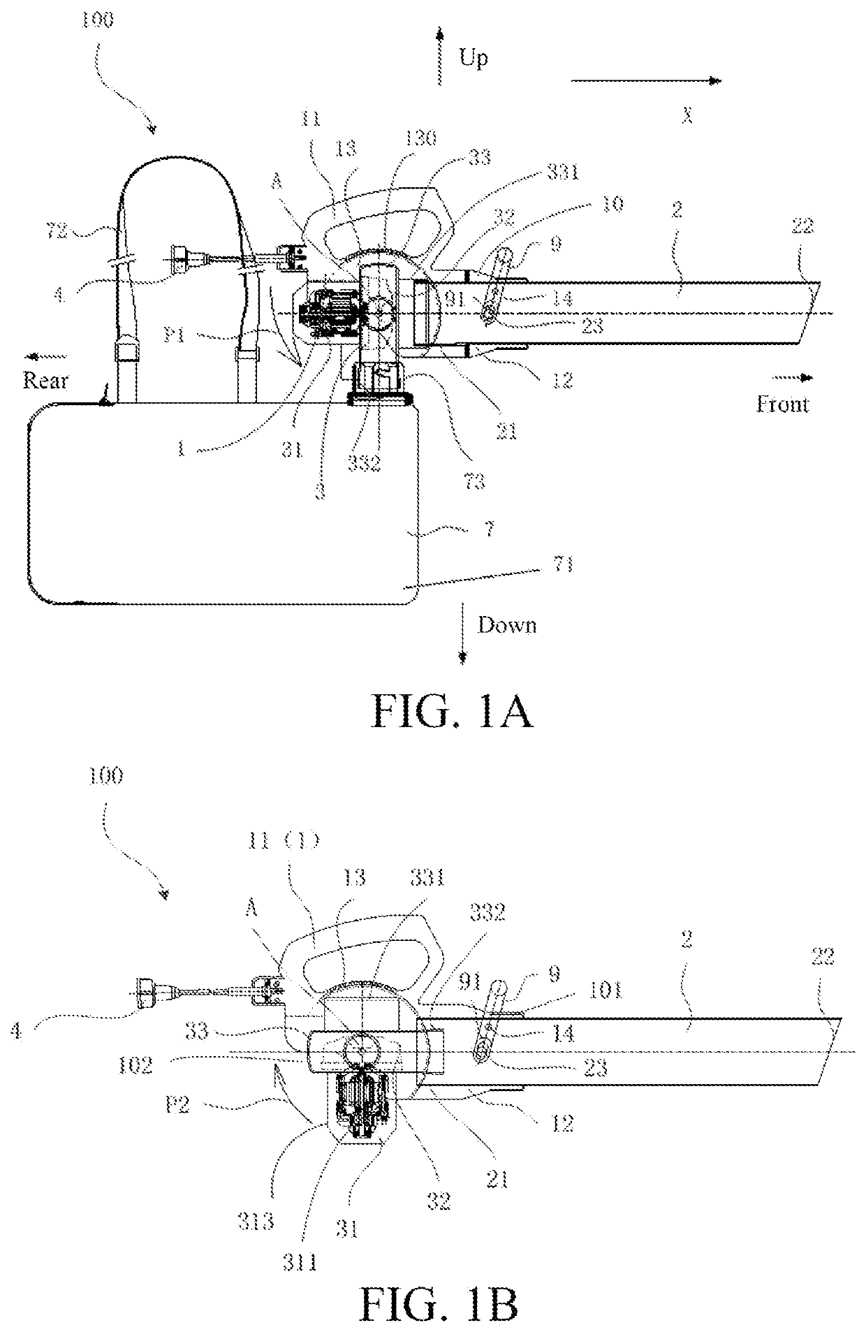
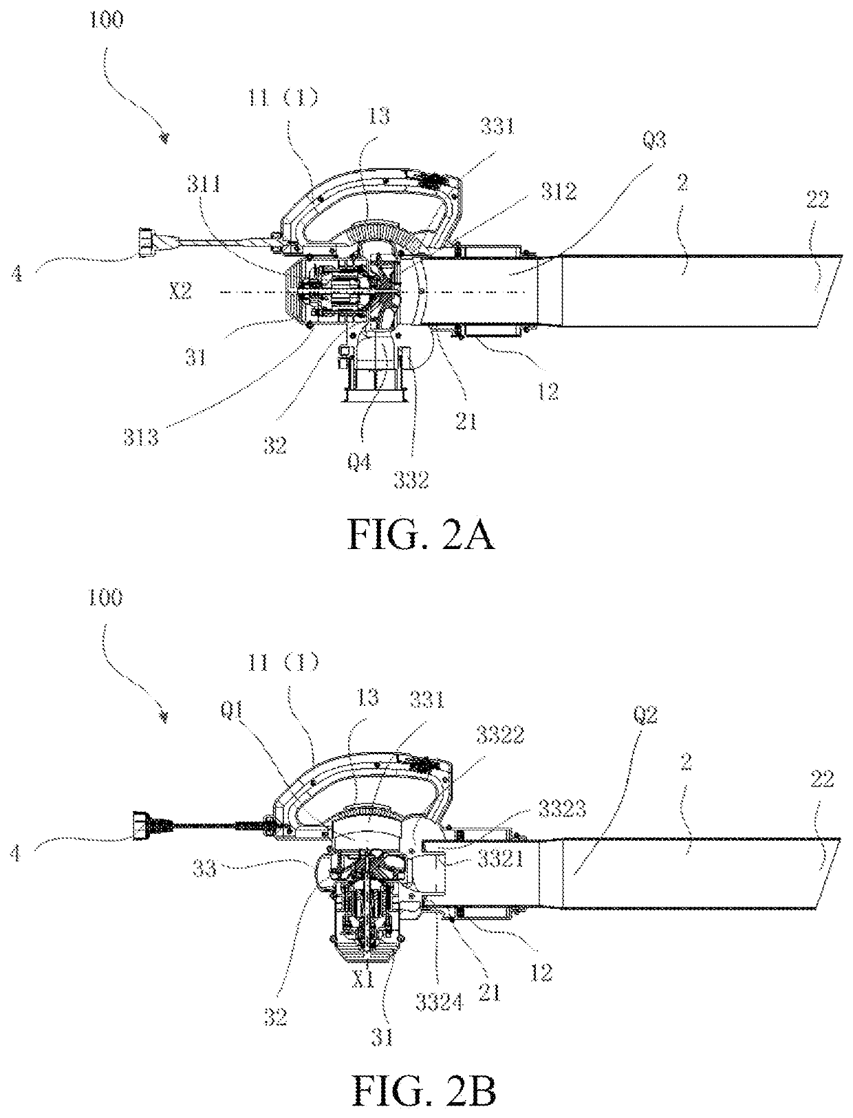
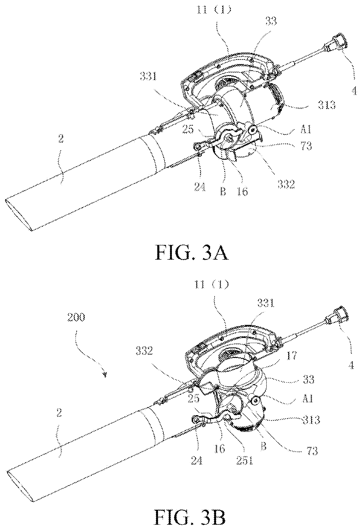
[0206]An overall structure of a single-tube blowing suction device according to the first embodiment of the present invention is first described.

[0207]As shown in FIG. 1A and FIG. 1B, the first embodiment of the present invention provides a single-tube blowing suction device (sometimes referred to as a “blowing suction device” for short) 100 for cleaning fallen leaves and twig pieces in a garden, including a body 1, a blowing-suction tube 2, and an airflow generation apparatus 3. Specifically, the blowing suction device 100 may use a blowing function to gather scattered leaves or may use a suction function to suck leaves into a specified garbage collection apparatus to implement cleaning. Therefore, the blowing suction device 100 has at least following two working modes. When the blowing suction device 100 is in a first working mode, the blowing suction device 1 performs the blowing function, and when the blowing suction device 100 is in a second working mode, the blowing suction de...

second embodiment

[0291]The second implementation of the present invention is described below with reference to FIG. 5.

[0292]In the first embodiment, the body air inlet portion 13 is located below the holding portion 11. However, the present invention is not limited thereto.

[0293]For example, in this embodiment, the body air inlet portion 13 includes an air inlet channel 132 located below the grip portion 11, an opening 130 located at one end of the air inlet channel 132, and an exit 133 located at the other end of the air inlet channel 132. The opening 130 is located on a front side of the grip portion 11. That is, the opening direction of the opening 130 is basically consistent with the extending direction of the blowing-suction tube. In the blowing mode, incoming air generally flows along an arrow 13A to enter the volute 33 through the body air inlet portion 13.

[0294]In this embodiment, the opening 130 of the body air inlet portion 13 faces a front-side opening of the body 1. Compared with that th...

third embodiment

[0296]The third embodiment of the present invention is described below with reference to FIG. 6A to FIG. 6C.

[0297]Referring to FIG. 1A, in the suction mode, the output shaft of the motor 31 is parallel to the central axis of the blowing-suction tube 2, and the motor 31 and the rotational axis A are located at approximately at the same height. Referring to FIG. 1B, in the blowing mode, the output shaft of the motor 31 is perpendicular to the central axis of the blowing-suction tube 2, and the motor body 311 is located below the rotational axis A.

[0298]Generally, the weight of the motor 31 accounts for a very large part in the weight of the entire airflow generation apparatus 3. During switching from the suction mode shown in FIG. 1A to the blowing mode shown in FIG. 1B, the center of gravity of the motor 31 lowers, so that the switching is facilitated. During switching from the blowing mode shown in FIG. 1B to the blowing mode shown in FIG. 1A, the center of gravity of the motor 31 r...


PUM


Abstract

The present invention provides a single-tube blowing suction device, including a body (1), an airflow generation apparatus, a collection apparatus, and a blowing-suction tube (2). The airflow generation apparatus has an air inlet portion and an air outlet portion. The airflow generation apparatus is rotatably mounted on the body (1). The airflow generation apparatus rotates relative to the body (1) to enable the single-tube blowing suction device to switch between a suction mode and a blowing mode. In the suction mode, the air inlet portion of the airflow generation apparatus is in fluid communication with a first end (21) of the blowing-suction tube (2), and the air outlet portion of the airflow generation apparatus is in fluid communication with a connection port of the collection apparatus. In the blowing mode, the air outlet portion of the airflow generation apparatus is in fluid communication with the first end (21) of the blowing-suction tube. In the single-tube blowing suction device of the present invention, one tube is used for both blowing and suction. It is not necessary to detach and change a blowing tube and a suction tube to switch between blowing and suction. It is only necessary to rotate the airflow generation apparatus relative to the body by a particular angle to implement switching between blowing and suction. The human-machine interaction is desirable, so that the use comfort and work efficiency is improved.

Description

[0001]This application is a Continuation Application of International Application No. PCT / CN2018 / 120684, filed on Dec. 12, 2018, which claims benefit of and priority to Chinese Patent Application No. 201711316309.1, filed on Dec. 12, 2017, all of which are hereby incorporated by reference in their entirety for all purposes as if fully set forth herein.BACKGROUNDTechnical Field[0002]The present invention relates to, and in particular, a single-tube blowing suction device.Related Art[0003]In some existing blowing suction devices, a blowing tube and a suction tube are detached and assembled alternately to implement switching between blowing and suction. In such a solution, a user needs to detach a blowing tube and a suction tube during use, resulting in complex operations, undesirable human-machine interaction, and inconvenient use.SUMMARY[0004]In view of the foregoing status in the prior art, one objective of the present invention is to provide a single-tube blowing suction device, so...

Claims


Application Information

Patent Timeline
IPC IPC(8): A01G20/47A47L5/14F04D23/00
CPCA01G20/47A47L5/14F04D23/003E01H1/0863E01H1/0809E01H1/0836F04D25/105F04D25/084
Inventor YU, XUEFENGJIAO, SHIPING
Owner POSITEC POWER TOOLS (SUZHOU) CO LTD
Why Eureka
Eureka Blog
Learn More