System and method for real-time visualization of radiation pattern

Active Publication Date: 2020-09-17
ROHDE & SCHWARZ GMBH & CO KG
View PDF3 Cites 1 Cited by
  • Summary
  • Abstract
  • Description
  • Claims
  • Application Information

AI Technical Summary

Benefits of technology

The invention provides a measurement system for real-time visualization of radiation pattern. The system has multiple antennas and detectors that provide a voltage gain based on a received radio signal. The voltage gain is then rectified and amplified using multiple amplifiers and receiving elements with light emitting diodes (LEDs) that optically visualize the radiation pattern. The use of RGB LEDs with multiple colors, preferably a multi-color LED, simplifies the measure and allows for easier assessment of signal strength. The system also includes tuning elements that adjust the amplified voltage of each amplifier based on the input voltage range of its associated LED. This improves system reliability.

Problems solved by technology

However, utilizing measurement probes to get sampled data, disadvantageously, require a subsequent evaluation logic that involves additional processing time and consequently the system fails to perform real-time measurement.

Method used


Image

  • System and method for real-time visualization of radiation pattern
  • System and method for real-time visualization of radiation pattern
  • System and method for real-time visualization of radiation pattern

Examples


Embodiment Construction

[0023]Reference will now be made in detail to the embodiments of the present invention, examples of which are illustrated in the accompanying drawings. Similar entities and reference numbers in different figures have been partially omitted. However, the following embodiments of the present invention may be variously modified and the range of the present invention is not limited by the following embodiments.

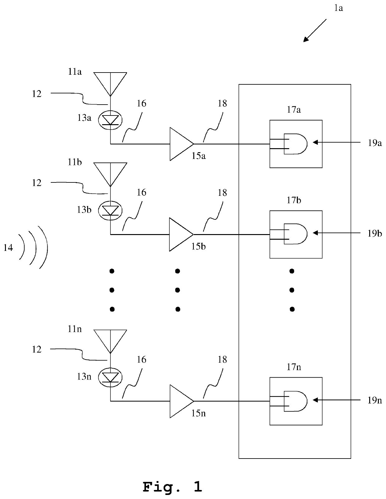
[0024]In FIG. 1, an exemplary embodiment of the inventive measurement system la for real-time visualization of radiation pattern is illustrated. In this context, the measurement system la comprises an antenna array with a plurality of antennas 11a, 11b, . . . , 11n configured to provide a voltage gain 12 corresponding to a received radio signal 14. Furthermore, the measurement system la comprises a plurality of radio frequency detectors 13a, 13b, . . . , 13n configured to rectify the voltage gain 12 from each antenna of the plurality of antennas 11a, 11b, . . . , 11n. The antenna ...


PUM


Abstract

A measurement system for real-time visualization of radiation pattern is provided. The measurement system comprises an antenna array with a plurality of antennas configured to provide a voltage gain corresponding to a received radio signal. Furthermore, the measurement system comprises a plurality of radio frequency detectors configured to rectify the voltage gain from each antenna of the plurality of antennas. In addition, the measurement system comprises a plurality of amplifiers downstream of the plurality of radio frequency detectors configured to amplify the magnitude of a rectified voltage from each of the radio frequency detectors. The measurement system moreover comprises a plurality of receiving elements, each includes a light emitting diode and configured to receive an amplified voltage corresponding to each amplifier of the plurality of amplifiers.

Description

TECHNICAL FIELD[0001]The invention relates to a measurement system and a corresponding measurement method for real-time visualization of radiation pattern, especially to perform measurements on radio frequency radiation to assess the signal strength and the radiation direction of the receiving signal.BACKGROUND ART[0002]For measuring radiation patterns, mechanically moving measuring probes are commonly used, which are moved in a lateral direction along the measurement axes and the corresponding radiation strength levels are sampled. Instead of the point by point measurement as described above, it is also possible to measure a radiation pattern by using a fixed measuring probe and by moving the device under test in a lateral direction with respect to the measurement axes.[0003]For example, CN 105242169 B demonstrates a measuring apparatus for a signal transmitting terminal and a signal receiving terminal of a distribution frame. The apparatus comprises a housing, a testing connector ...

Claims


Application Information

Patent Timeline
IPC IPC(8): G01R29/08H04B10/50
CPCG01R15/245G01R15/241G01R15/247G01R15/242G01R15/246H04B10/502G01R33/0322G01R19/0092G01R15/24G01R29/0885G01R29/0857G01R29/08G01R29/10
Inventor HEUEL, STEFFENSCHOCH, ANDRESTEFFENS, JOHANNES
Owner ROHDE & SCHWARZ GMBH & CO KG
Why Eureka
Try Eureka