Timepiece comprising a mechanical movement which running is enhanced by a regulation device

Active Publication Date: 2020-09-10
THE SWATCH GRP RES & DEVELONMENT LTD
View PDF0 Cites 0 Cited by
  • Summary
  • Abstract
  • Description
  • Claims
  • Application Information

AI Technical Summary

Benefits of technology

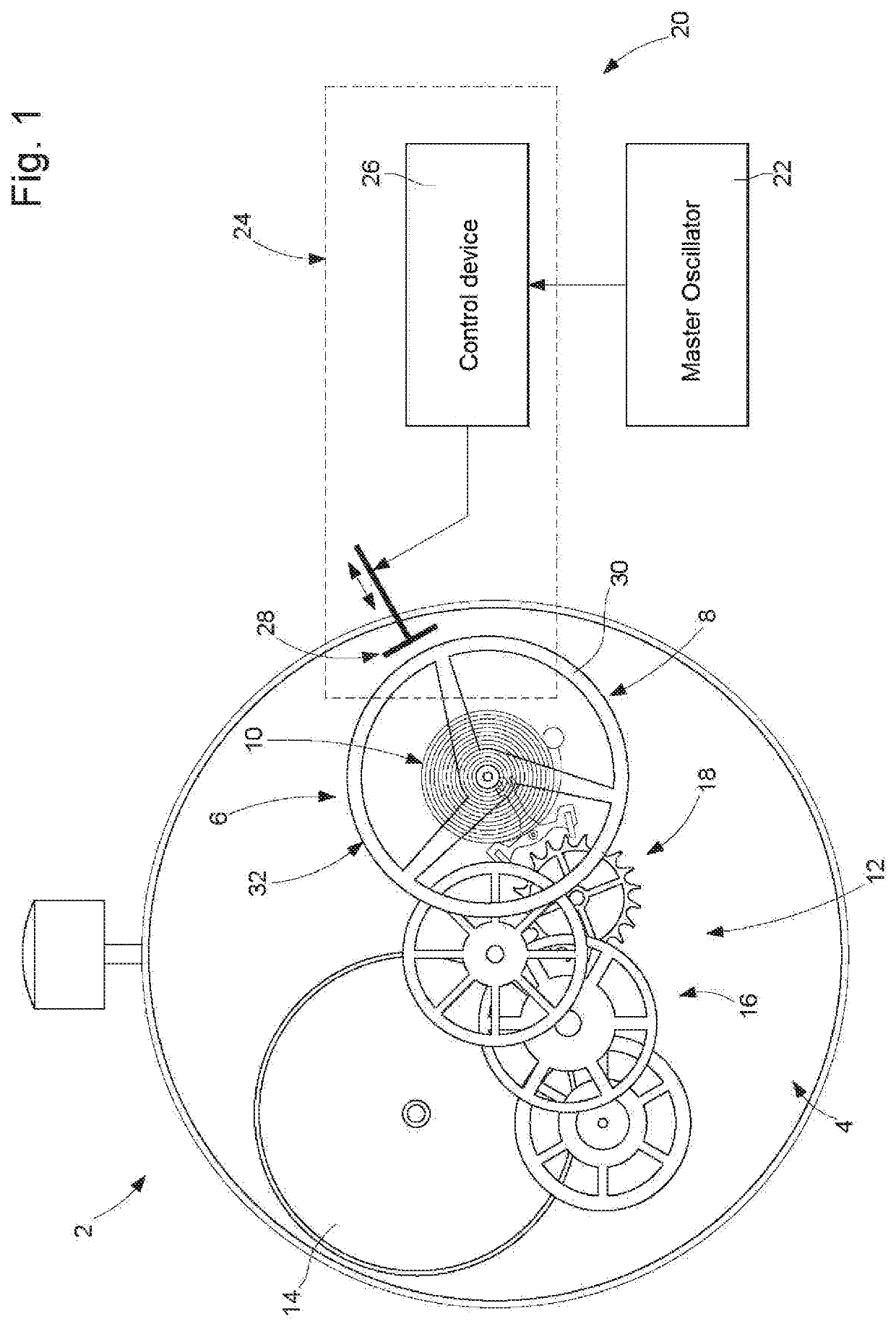
The present invention seeks to enhance the precision of a mechanical timepiece movement by correcting its running and reducing the daily time drift. This is particularly important for a movement that is initially optimally adjusted. The invention provides a device that can correct the time drift of a mechanical movement without compromising its ability to function autonomously with the best possible precision.

Problems solved by technology

The use of a magnet-coil type electromagnetic system for coupling the balance-hairspring with the electronic regulation circuit gives rise to various problems.
First, the arrangement of permanent magnets on the balance results in a magnetic flux being constantly present in the timepiece movement and in this magnetic flux varying spatially periodically.
Such a magnetic flux may have a harmful action on various members of elements of the timepiece movement, particularly on elements made of magnetic material such as parts made of ferromagnetic material.
This may have repercussions on the proper operation of the timepiece movement and also increase the wear of pivoted elements.
Such screening tends to increase the size of the mechanical resonator and the weight thereof.
Furthermore, it limits the aesthetic configuration possibilities for the balance-hairspring.
Such a regulation system has numerous drawbacks and it could seriously be doubted that it could form an operational system.
The periodic actuation of the finger relative to the oscillation movement of the stop and also a potentially large initial phase shift, for the oscillation of the stop with respect to the periodic movement of the finger towards this stop, pose a number of problems.
Such parasitic interactions may damage the mechanical oscillator and / or the actuator.
Furthermore, this limits practically the tangential range of the finger.
Finally, the holding duration of the finger in the interaction position with the stop must be relatively short, therefore limiting a correction inducing a delay.

Method used


Image

  • Timepiece comprising a mechanical movement which running is enhanced by a regulation device
  • Timepiece comprising a mechanical movement which running is enhanced by a regulation device
  • Timepiece comprising a mechanical movement which running is enhanced by a regulation device

Examples


second embodiment

[0063]In an alternative embodiment, the braking force applied to the balance is envisaged to be axial. In such an alternative embodiment, it is advantageous to envisage a mechanical braking device of the type of the second embodiment, i.e. with two braking pads arranged axially facing one another and between which the felloe of the balance particularly passes. Thus, the actuator is arranged such that, upon the application of the braking pulses, the two pads apply to the balance two substantially aligned axial forces of opposite directions The force couple applied by each of the two pads during a braking pulse is envisaged herein also substantially equal to the other.

first embodiment

[0064]A timepiece 80 according to a third particular embodiment is shown in FIG. 5. It differs from the first embodiment essentially by the choice of the actuator which comprises a timepiece type motor 86 and a braking member 90 which is mounted on a rotor 88 (having a permanent magnet) of this motor so as to apply a certain force on the felloe of the balance 8 of the resonator 6 when the rotor performs a certain rotation, which is induced by a power supply 82 of a motor coil during the braking pulses in response to a control signal supplied by a control signal supplied by the control circuit 40.

[0065]According to various alternative embodiments, the electromechanical actuator comprises a piezoelectric element or a magnetorestrictive element or, to actuate said braking member, an electromagnetic system.

[0066]There will be described hereinafter, with reference to FIGS. 6 and 7, a remarkable physical phenomenon highlighted within the scope of developments resulting in the present inve...


PUM


Abstract

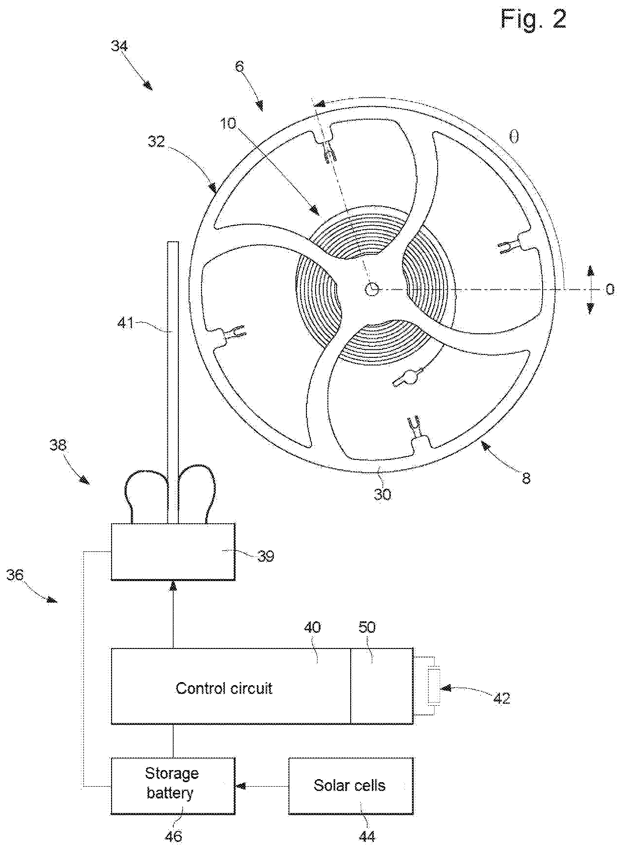
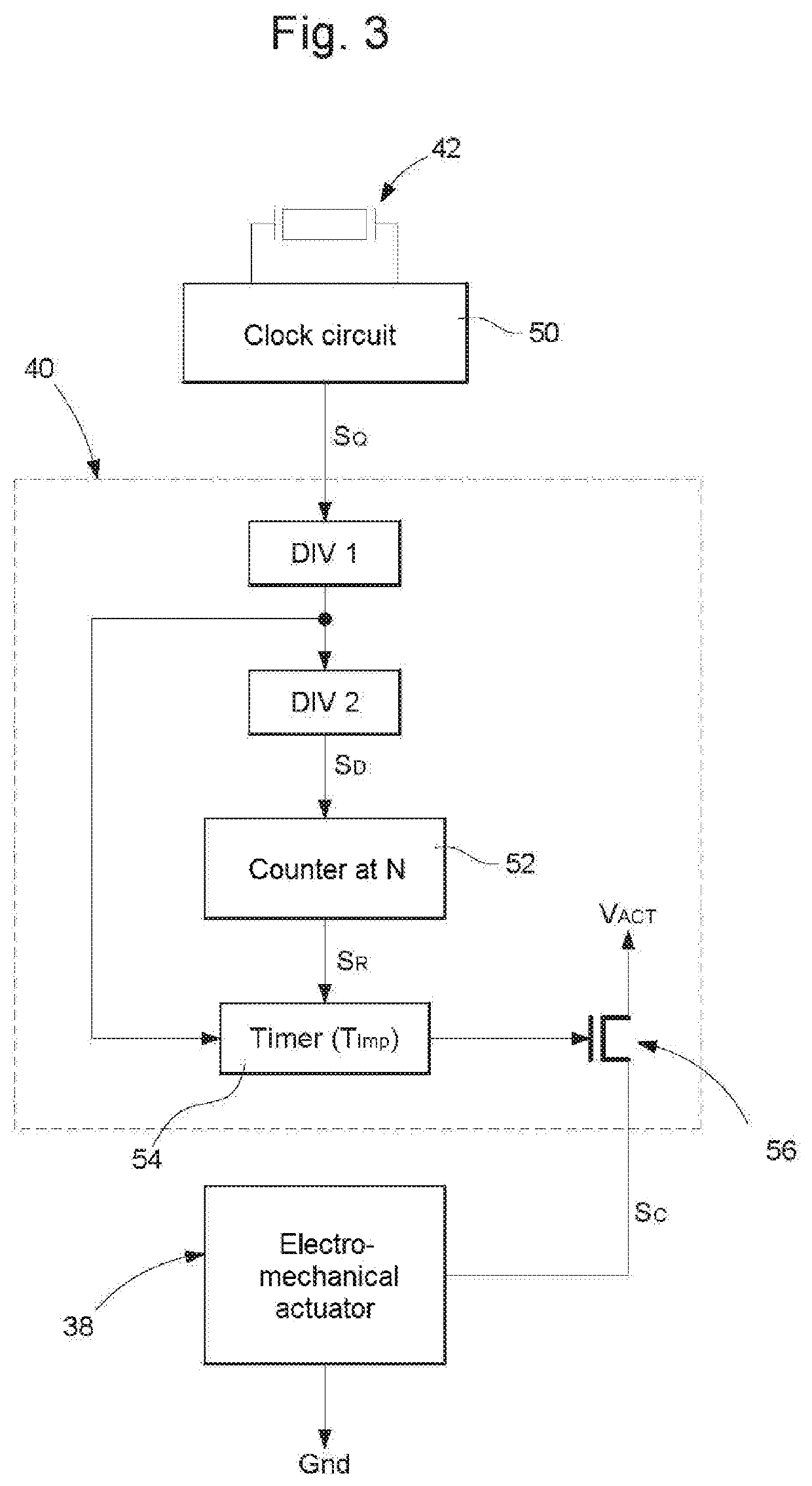
A timepiece with a mechanical movement which includes an indicator mechanism of at least one time data item, a mechanical resonator forming a mechanical oscillator which paces the running of the indicator mechanism, and a regulation device to prevent a potential time drift in the running of the indicator mechanism. The regulation device is formed by a master oscillator and a mechanical braking device of the mechanical resonator, this mechanical braking device being arranged to be able to apply periodically to the mechanical resonator braking pulses at a braking frequency determined by the master oscillator. The system, formed of the mechanical resonator and the mechanical braking device, is configured so as to enable the mechanical braking device to be able to start the braking pulses at any position of the mechanical resonator. The braking pulses have a duration less than one quarter of a set-point period.

Description

TECHNICAL FIELD[0001]The present invention relates to a timepiece comprising a mechanical movement wherein the running thereof is enhanced by a device for correcting a potential time drift in the operation of the mechanical oscillator, which paces the running of the mechanical movement.[0002]In particular, the timepiece is formed, on one hand, by a mechanical movement comprising:[0003]an indicator mechanism of at least one time data item,[0004]a mechanical resonator suitable for oscillating along a general oscillation axis about a neutral position corresponding to the minimum potential energy state thereof,[0005]a maintenance device of the mechanical resonator forming therewith a mechanical oscillator which is arranged to pace the running of the indicator mechanism, each oscillation of this mechanical oscillator defining an oscillation period,[0006]and, on the other hand, by a device for correcting a potential time drift in the operation of the mechanical oscillator. Such a time dri...

Claims


Application Information

Patent Timeline
IPC IPC(8): G04C3/04H03B5/32H03B5/40G04C13/02
CPCH03B5/32G04C13/028H03B5/40G04C3/045
Inventor TOMBEZ, LIONEL
Owner THE SWATCH GRP RES & DEVELONMENT LTD
Why Eureka
Try Eureka