Automatic image registration of scans for image-guided surgery

Active Publication Date: 2020-09-10
BRAINLAB
View PDF0 Cites 1 Cited by
  • Summary
  • Abstract
  • Description
  • Claims
  • Application Information

AI Technical Summary

Benefits of technology

[0035]at least one of at least one recess or at least one projection is provided on an external surface (in one example, at only one for example predetermined location on the

Problems solved by technology

The fiducials may cause artefacts and therefore deteriorate the image quality of the 3D scan.
Furthermore, not only the m

Method used


Image

  • Automatic image registration of scans for image-guided surgery
  • Automatic image registration of scans for image-guided surgery
  • Automatic image registration of scans for image-guided surgery

Examples


Example

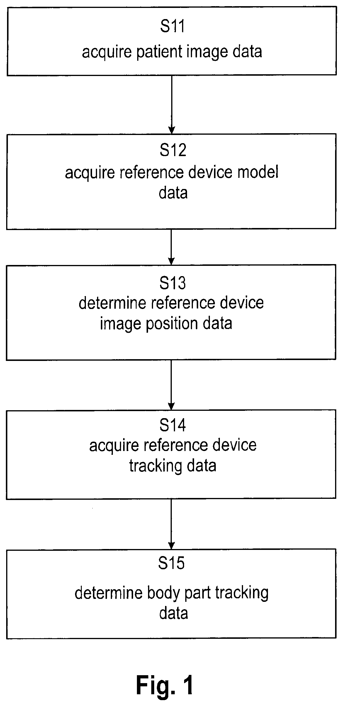
[0084]FIG. 1 is a flow diagram illustrating the basic steps of the disclosed method in accordance with the first aspect, which in the illustrative example of FIG. 1 starts with a step S11 of acquiring the patient image data. In subsequent step S12, the reference device model data is acquired, followed by step S13 which encompasses determining the reference device image position data. Then, step S14 acquires the reference device tracking data. Steps S11 to S14 serve as input steps for the last step shown in FIG. 1 which is step S15 encompassing determination of the body part tracking data.

[0085]A specific example of using the setup of FIG. 10 or a setup being technically equivalent to the setup of FIG. 10 comprises the following method steps, which fall into the scope of the method in accordance with the first aspect:

1. The tracking markers of the first reference device are registered to the second reference device (also called dynamic reference) before or after taking the scan for g...


PUM


Abstract

Provided is a method for determining a position of an imaged anatomical body part of a patient. The method includes acquiring patient image data describing a digital image of at least part of a reference device and the anatomical body part, acquiring reference device model data describing a model of at least one of at least one internal surface or at least one external surface of the reference device, determining, —based on the patient image data and the reference device model data, reference device image position data describing a relative position between the reference device and the anatomical body part, acquiring reference device tracking data describing a position of the reference device in the tracking reference system, and determining, based on the reference device image position data and the reference device tracking data, body part tracking data describing a position of the anatomical body part in the tracking reference system.

Description

[0001]The present invention relates to a computer-implemented method for determining a position of an imaged anatomical body part of a patient in a tracking reference system, a corresponding computer program, a non-transitory program storage medium storing such a program and a computer for executing the program, as well as a system for supporting determining a transformation defining a geometric relationship between a position of an anatomical body part of a patient in an image reference system and a position of the anatomical body part in the tracking reference system, the system comprising an electronic data storage device and the aforementioned computer. Furthermore, the present invention relates to a reference device for use in a navigated medical procedure and use of the reference device.TECHNICAL BACKGROUND[0002]Currently, automatic registration of an anatomical body part to a tracking reference system is performed by attaching markers to a scanner, calibrating image space rel...

Claims


Application Information

Patent Timeline
IPC IPC(8): G06T7/00A61B34/10A61B34/20G06T7/73G06T7/20
CPCG06T2207/30204A61B2034/2072G06T2207/30012A61B2034/2057G06T7/0012A61B34/20A61B2034/105A61B2034/102A61B34/10G06T7/20A61B2034/2051G06T7/75G06T2207/10072G06T2207/10116A61B2090/3983A61B2034/2055
Inventor ESSENREITER, ROBERTSCHWITZKO, RALFBERTRAM, MICHAELDREXL, THOMASHAIMERL, MARTIN
Owner BRAINLAB
Why Eureka
Try Eureka