
Active long track cover

a long track and seat technology, applied in the field of sliding seats, can solve the problems of limited track(s), track(s) being exposed to other activities inside the passenger compartment, seat sliding forward and rearward, etc., to achieve the effect of minimizing debris from entering the track, improving package size, and low profil

Active Publication Date: 2020-09-03
KEIPER SEATING MECHANISMS CO LTD
View PDF0 Cites 1 Cited by
  • Summary
  • Abstract
  • Description
  • Claims
  • Application Information

AI Technical Summary

Benefits of technology

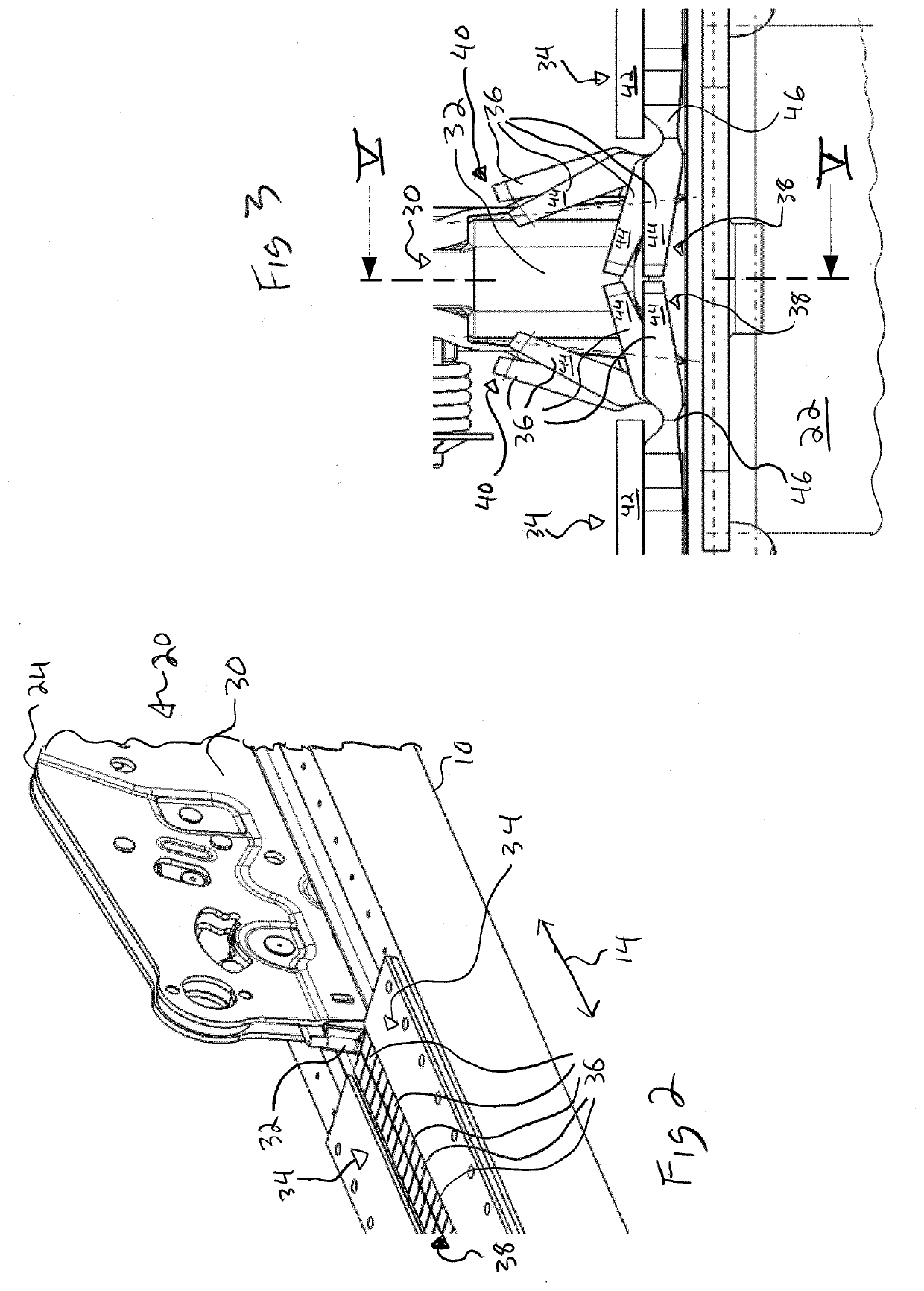
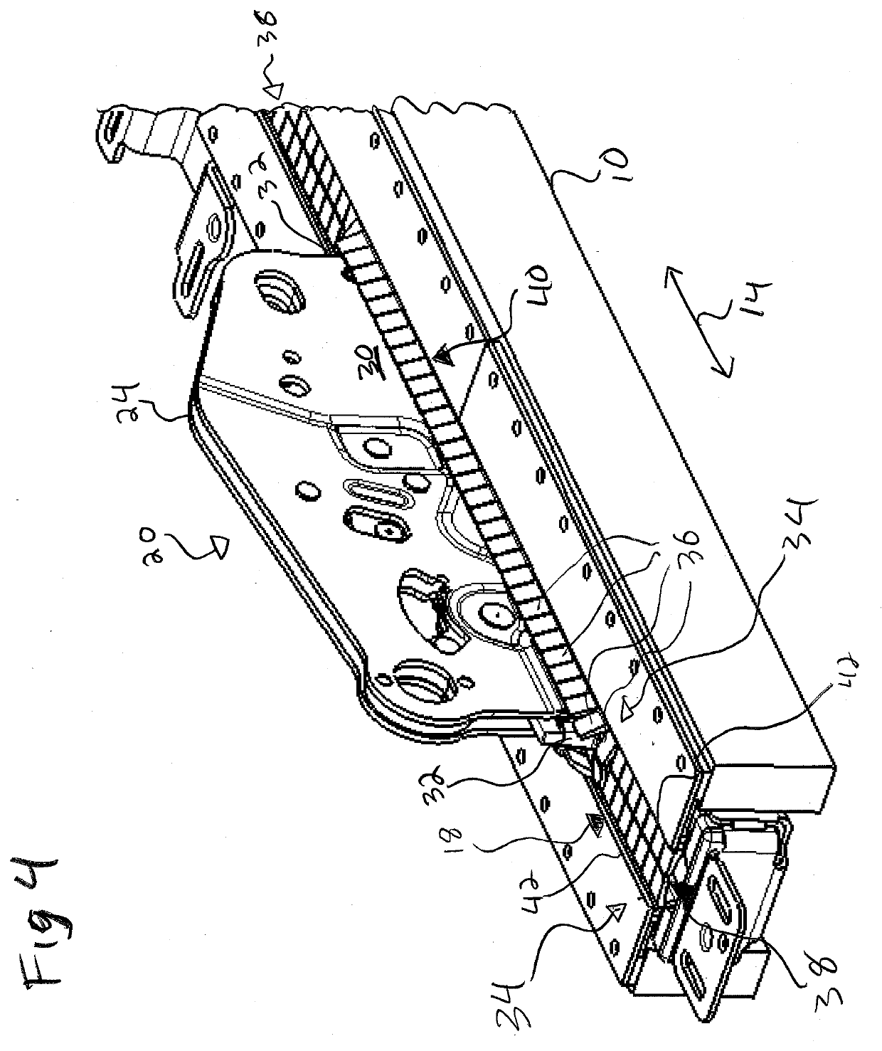
The present invention provides a vehicle seat assembly with a long track system, which can have a length of 1 meter or longer. The assembly includes a cover that covers the slots exposed by the longer tracks, while still allowing the seat to move smoothly in the track. The cover has a low profile and can be used with existing floor designs. The cover has a simplified manufacturing and assembly process, and is compatible with existing carriage / track assemblies with little or no modification. The cover has a plurality of fingers that move to open and close as the track carriages move down the track, providing a path for the carriage to move without interfering with the cover. The track has first and second longitudinal slot sides, and the fingers on the slot sides extend across the slot to allow for easy shaping and minimize interference with the feet of an occupant or cargo. The cover can be a separate structure that can be used in both long and short versions of the track. The dimensions of the fingers are relatively short compared to the track, and the fingers have a shorter dimension in the longitudinal direction of the track to minimize interference.

Problems solved by technology

Often, the amount that the seats were slidable forward and rearward, is limited to accommodate the range of different sizes for most of the people driving the car, and to accommodate most of the desired variations in leg room.
A disadvantage of such a track, or set of tracks, is that the track(s) are then not covered by the seat, and the track then is exposed to the other activities inside the passenger compartment.
This can be unsightly, and interfere with activities in the passenger compartment.
Debris from activities in the passenger compartment, such as from passengers, or cargo, can also enter into the tracks and hinder, or prevent, the seats / carriages from properly sliding in the tracks.
While the track can be recessed into the floor of the passenger compartment, this still leaves the slot open to the passenger / cargo compartment, which still can be unsightly, interfere with activities, such as the shoes of the passengers, and is especially prone to collect debris.
Collecting debris is especially disadvantageous, because it can prevent can hinder, or even completely prevent, the sliding of the seats in the track.
However these covers can be difficult to manufacture, difficult to maintain, prone to failure, and inadequately prevent the slot from being unsightly, interfering with activities, and preventing debris from passing through the slot into the interior of the track.
This structure would not be suitable when the track mounted to the vehicle extends the full length of the passenger / cargo compartment, especially when there are a plurality of seats sliding on the same track or set of tracks.
Also engaging and disengaging is prone to failure which can make the cover not cover the exposed track.
This cover does not protect openings on the top of the track from interfering with passengers, or from debris entering the track.
This causes a great deal of friction and resistance to moving of the seat, especially when dirt gets into the sliding connection between the endless belt and the stationary rails.
Furthermore because of the overlapping arrangement, U.S. Pat. No. 8,393,590 is not suitable for tracks which have a length which is several multiples of the overall front to back length of the seat.
Large sections of the track are exposed each time the cover is lifted, and require relatively large amounts of force when the seat is moved to lift a new cover.
This is disadvantageous for making minute adjustments to the position of the seat.

Method used


Image

  • Active long track cover
  • Active long track cover
  • Active long track cover

Examples


Embodiment Construction

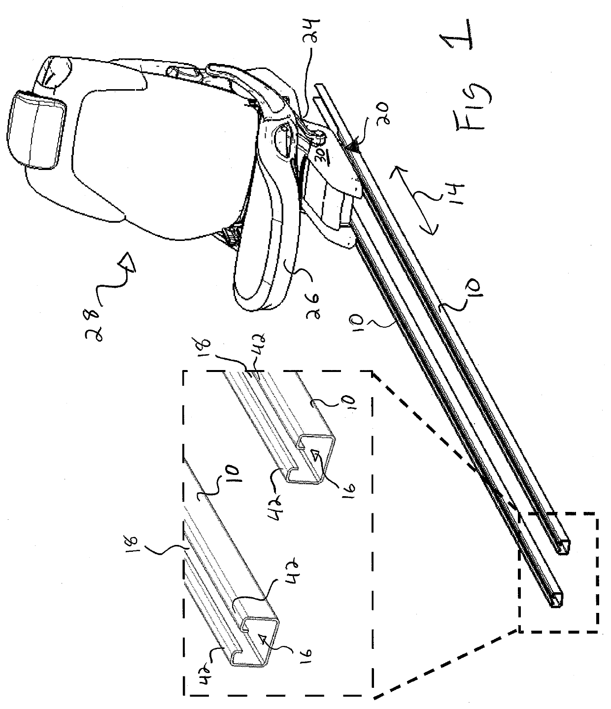
[0035]Referring to the drawings in particular, FIG. 1 shows a seat 28 slidably mounted on a track 10 through a carriage 20. The track 10 is much longer than the front to back distance of the seat 28. In the embodiment of FIG. 1, the track 10 extends in front of the seat base 26, and would be in the leg area or foot well 50, of an occupant of the seat 28.

[0036]The track 10 defines an interior space 16 and a slot 18 which opens the interior space 16 to the area surrounding the track 10. Inside track 10, a slide 22 of the carriage 20 is slidable mounted onto the track 10, as schematically shown in FIG. 5. The carriage 20 includes an extension 30 which is connected to the slide 22, and extends away from the slide 22. The extension 30 passes through the slot 18, and the end of the extension 30 diametrically opposite the slide 22 has a base support 24 which attaches to the seat base 26 of the vehicle seat 28 to support the seat base 26 and the vehicle seat 28.

[0037]The slide 22 is contain...


PUM


Abstract

A vehicle seat assembly with a long track that significantly extends beyond the seat. The track defines a slot. A carriage is movable along the track through the slot. A cover is mounted on the track, and includes a plurality of fingers being individually pivotally connected to the track between a cover position and an open position. Each finger in the cover position blocking a portion of the slot from the area outside of the track. Each finger in the open position opening a respective portion of the slot to the area outside of the track. The plurality of fingers and the longitudinal edges of the extension being shaped configured to move the plurality of fingers from the cover position to the open position as the carriage moves along the track and against the plurality of fingers.

Description

FIELD OF THE INVENTION[0001]The present invention relates to a sliding seat in a vehicle, and in particular to the track, the carriage that slides in the track, and the seat that is supported by the carriage.BACKGROUND OF THE INVENTION[0002]Seats are preferably slidable in vehicles in order to accommodate people of different sizes. This is especially true for the driver's seat, since occupants of different sizes will need the seats at different positions to best handle the controls of the vehicle. The front passenger seat is also often made slidable, in order to give the front passenger more or less leg room. If there is no rear passenger, the front passenger seat can be slid more rearward, to give the front passenger a large amount of leg room. If there is a rear passenger, the front passenger seat is often slid forwards or backwards, to divide up the desired amount of leg room for the front and rear passenger.[0003]Often, the amount that the seats were slidable forward and rearwar...

Claims


Application Information

Patent Timeline
Patent Type & Authority Applications(United States)
IPC IPC(8): B60N2/07
CPCB60N2/0715B60N2/0732B60N2/0725
Inventor KAPUSKY, MICHAELSANSUDDI, SHREYASWOLKOWICZ, JOSEPH A.
Owner KEIPER SEATING MECHANISMS CO LTD
Learn More