
Wind turbine generator for low to moderate wind speeds

Active Publication Date: 2020-08-27
21ST CENTURY WIND INC
View PDF0 Cites 2 Cited by
  • Summary
  • Abstract
  • Description
  • Claims
  • Application Information

AI Technical Summary

Benefits of technology

The invention is a wind turbine generator with a unique design that overcomes the challenges of using wider blades in wind turbines. The blades have a specific shape and are stiffened at the root to prevent bending under high winds. The use of a plate-type modular hub and a stiff blade root also prevents the blades from flexing and colliding with the support tower. The generator includes a nacelle with a support plate and a gear train to an input shaft of a generator. The support tower is a low-weight, modular plate-type support tower that reduces pressure on the foundation and allows for the use of a thinner foundation. The power conditioning components are located outside of the support tower to protect them from damage and improve their life span. Overall, the invention has improved energy output and reduced maintenance costs.

Problems solved by technology

While such a design is capable of generating significant power in low to moderate wind speeds of between 6.0 and 7.5 m / s, the applicant has observed a number of shortcomings in such a design strategy that limits it overall ability to efficiently convert wind to electrical energy.
First, the long, narrow aspect ratio of conventional blades used in such designs limits the specific power of the three-bladed rotor to between about 231-241 watts per square meter (W / m2).
The resulting stresses on the hub and bending forces applied to the drive shaft would accelerate the fatigue and wear on the hub as well as the gears within the gearbox such that the resulting additional maintenance expenses would negate the advantages associated with any increases in efficiency.
Second, the applicant has observed that the wound coil-type generators used in prior art wind turbines lose a substantial amount of efficiency at the lower rotor speeds associated with the lower wind speeds.
However, such a solution would render the gearbox more vulnerable to damage if wider blades were used due to the increased bending forces associated with such wider blades.
Such increased bending forces would cause the internal gears of the gear box attached to the rotor drive shaft to periodically squeeze against other gears or shafts, thereby accelerating wear and maintenance procedures.
Finally, the applicant has observed that the one-piece, cast hubs used in wind multi MW turbines are often so large and heavy that they cannot be cost-effectively transported to many moderate to low wind areas.
Even when such transportation is feasible, the need to raise such heavy single-piece cast hubs to the top of the support tower makes assembly of the wind turbine difficult.
Single-piece cast hubs are difficult to manufacture because of their large size, and must be rejected upon final inspection if any one portion does not conform to specification.
Consequently, such conventional, single-piece cast hubs have a high manufacturing rejection rate of nearly 50%.

Method used


Image

  • Wind turbine generator for low to moderate wind speeds
  • Wind turbine generator for low to moderate wind speeds
  • Wind turbine generator for low to moderate wind speeds

Examples


Embodiment Construction

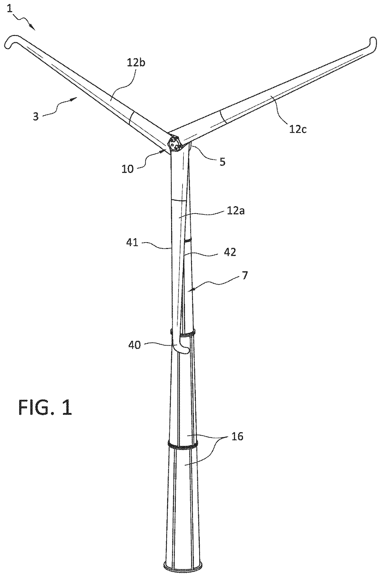
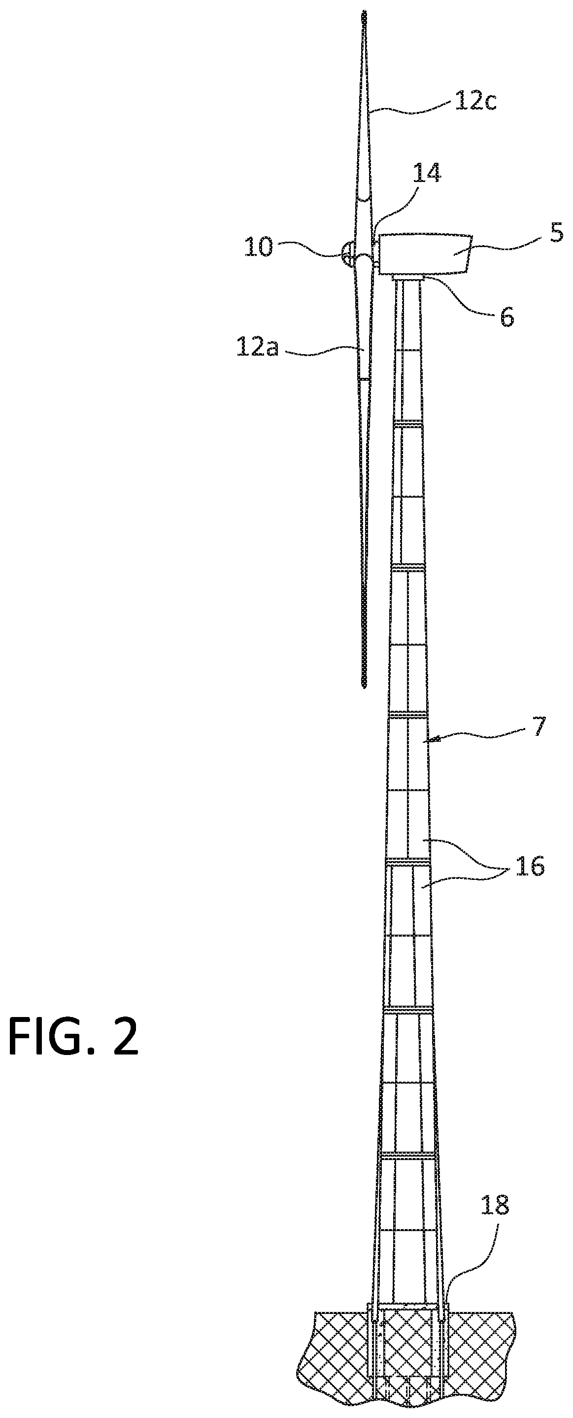
[0033]With reference to FIGS. 1 and 2, the wind turbine generator 1 of the invention generally comprises a rotor 3, a nacelle 5 containing a gearbox and a generator, and a support tower 7 formed from a plurality of interconnectable plates 16. The bottom end of the support tower is mounted on a disc-shaped foundation 18 buried in the surrounding soil. The nacelle 5 is rotatably connected to the top end of the support tower by means of a yaw bearing 6. The rotor 3 and nacelle 5 are maintained in an orthogonal orientation with respect to the wind by means of the yaw bearing 6 and yaw motors (not shown) contained within the nacelle 5.

[0034]The rotor 3 includes a hub 10, three blades 12a, 12b, and 12c angularly spaced 120° from one another, and a driveshaft 14. The driveshaft 14 is connected at one end to the hub 10, and to the gearbox (not shown in FIGS. 1 and 2) within the nacelle 5.

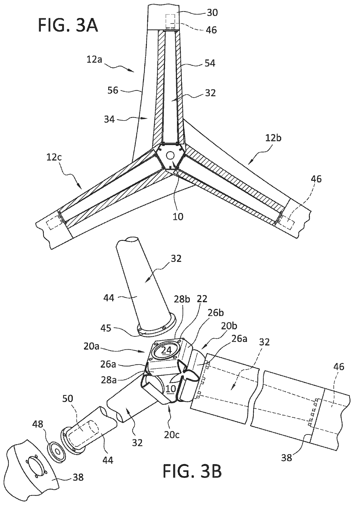
[0035]With reference now to FIGS. 1, 3A, and 3B, the hub 10 is a modular hub formed from three interconn...


PUM


Abstract

A 3 megawatt wind turbine generator having a rotor configured to efficiently extract power from low to moderate winds having an average speed of between about 7.5 and 8.5 meters / second is provided. The rotor includes three aerodynamic blades having an aspect ratio of 15 mounted on a modular hub. The relatively shorter and wider aerodynamic blades result in a rotor having a specific power of about 0.27, a specific power rating of about 260 watts / m2, and a solidity of about 6%. The modular hub is formed from three interconnected hub sections, each of which formed from a single plate of spring steel bent along its sides into a modular shape. The bends in the plates forming the hub sections act like corrugations that more strongly resist the larger stresses applied to the hub as a result of the relatively shorter and wider aspect of the aerodynamic blades.

Description

FIELD OF THE INVENTION[0001]This invention relates to wind turbine generators, and is specifically concerned with a wind turbine generator having a rotor configured to efficiently extract power from low to moderate winds having an average speed of between about 7.5 and 8.5 meters / second.BACKGROUND OF THE INVENTION[0002]Wind turbine generators constitute an important and growing segment of renewable energy production, and energy production in general. In July of 2008, the U.S. Department of Energy published a report outlining a goal of increasing wind energy's contribution to the U.S. energy supply to 20% by 2030. Some states have outlined even more ambitious plans. In October of 2015, Governor Brown of California signed legislation requiring 50% of that state's energy to come from renewable energy sources, with wind energy being a substantial contributor to the increase. In his State of the State address in January of 2019, Governor Cuomo of New York proposed quadrupling that state'...

Claims


Application Information

Patent Timeline
IPC IPC(8): F03D15/00F03D9/25F03D7/02F03D80/70H02K7/116H02K7/18
CPCH02K7/1838F03D7/0224F03D15/00H02K7/116F03D80/70F03D9/25F03D1/0675F05B2240/311Y02E10/72
Inventor MILLER, WILLIAMHANSEN, PEDER MØRCK
Owner 21ST CENTURY WIND INC
Learn More