Method for operating a control unit, and device having an associated control unit

a control unit and associated control technology, applied in the direction of detecting faulty computer hardware, vehicle components, power-on test, etc., can solve the problems of frequent delay in the availability of the control unit, accidents may occur during the driving operation of the vehicle, etc., to achieve rapid response to an event, high reliability, and the effect of rapid respons

Active Publication Date: 2020-07-30
ROBERT BOSCH GMBH
View PDF0 Cites 0 Cited by
  • Summary
  • Abstract
  • Description
  • Claims
  • Application Information

AI Technical Summary

Benefits of technology

[0015]The execution of the second start sequence for setting the control unit to the second mode preferably takes place in response to a trigger signal supplied by a sensor unit. Thus, it is possible to dispense with an interaction with a user, meaning that the control unit is available for use in a particularly rapid manner. The sensor unit especially includes a sensor which is suitable for detecting an event in the environment of a vehicle. The second system particularly includes the sensor unit. In this context it is advantageous if both the second system and the control unit are activated by the sensor unit. Such a system is capable of a very rapid response to an event that is detected by the sensor unit.
[0016]It is furthermore advantageous if the control unit is a control electronics for a sensor, in particular for a camera system. If the control unit is a control electronics for a camera system, then images from the camera system are able to be supplied in the first mode and it is ensured that the images do not include any errors, or the images may be provided in the second mode so that images can be supplied very rapidly. Using the first system and the second system, it is therefore possible to make functions available that respond to an event either in a rapid or in a highly reliable manner. This particularly prevents the second system from responding to an event too late. The camera system is what is called an NTC system, in particular.
[0017]It is furthermore advantageous if the additional self-test is carried out following a start-up of the control unit during which the second start sequence was executed, in response to a request for setting the control unit to the first mode. This means that the control unit, once it is in the second mode, is set to the first mode in response to the request. The self-test thus is carried out retroactively. For this purpose, the control unit is particularly started up anew and the first start sequence is executed in full or the self-test is otherwise carried out retroactively in an independent manner. For example, this makes it possible for the second system to rapidly respond to an event but subsequently also allows for a safe operation of the first system.
[0018]During the start-up of the control unit, a switch is preferably first set to a first position, and at the end of the first start sequence the switch is set to a second position, the switch being configured to prevent an execution of a safety-relevant function when the switch is in the first position. This prevents information or functions provided by the control unit from being used by the first system already prior to the conclusion of the start operation of the control unit, i.e. the start-up of the control unit. In addition, a generally usable indicator is made available, which may be used by a variety of different devices for querying whether the control unit is suitable for supplying safety-relevant information or functions. The switch consequently is an indicator of the mode currently assumed by the control unit. The switching circuit with the switch is particularly developed as a failsafe switching circuit. This means that the control unit actuates the switch in such a way that it is in the first position if an error has occurred in the control unit or in the switch. It is pointed out here that the switch may be in the first position during the neutral state, meaning that setting the switch to the first position does not cause any physical movement of the switch.

Problems solved by technology

However, while it is often required that a control unit be rapidly available, such an availability of the control unit is frequently delayed on account of the self-test.
If an operativeness of the control unit is not ensured because the self-test has not been carried out, then accidents may happen during a driving operation of the vehicle.
The vehicle monitoring system thus is a system that is not safety-relevant because information is simply recorded or an accident is already precluded by the fact that the vehicle is not moving, i.e., is at a standstill.

Method used


Image

  • Method for operating a control unit, and device having an associated control unit
  • Method for operating a control unit, and device having an associated control unit

Examples


Embodiment Construction

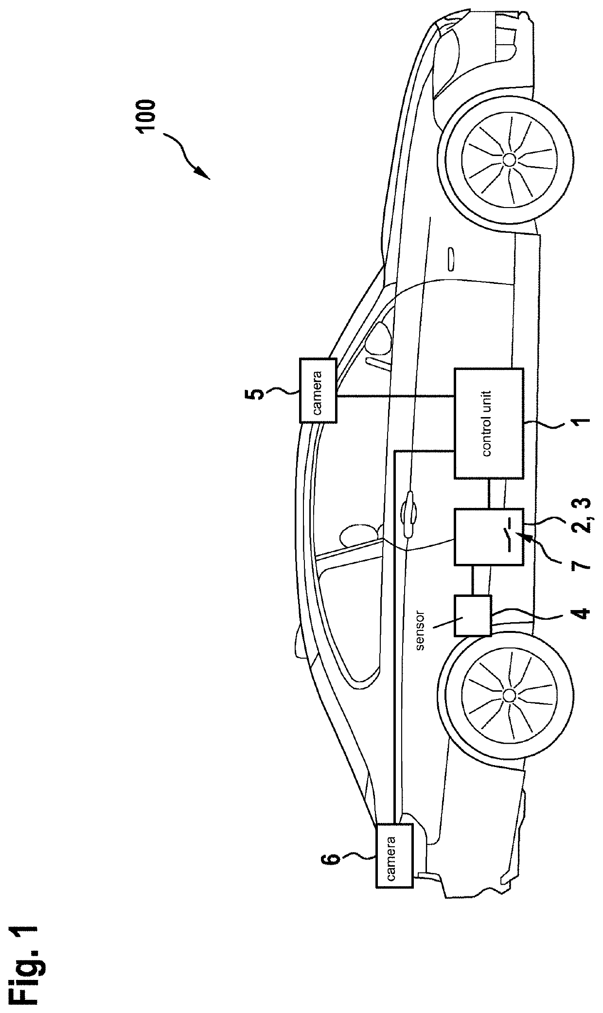
[0023]FIG. 1 shows a vehicle 100. A control unit 1, which is able to be brought into an operative state by its start-up, is situated in vehicle 100.

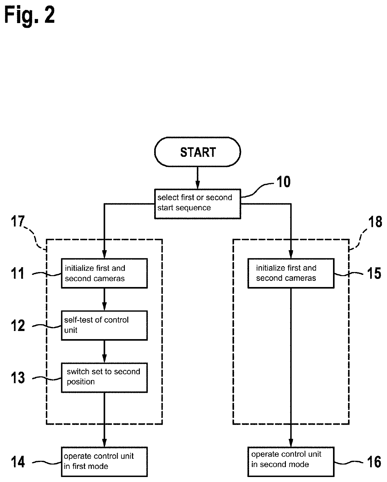
[0024]Control unit 1 is an electronic control unit which includes a control electronics of a camera system. In the exemplary embodiment described here, a first camera 5 and a second camera 6 are therefore coupled with control unit 1. First camera 5 and second camera 6 acquire an environment of vehicle 100. Cameras 5, 6 transmit the acquired images from camera 5, 6 to control unit 1, which makes them available for further use by other system 2, 3 of vehicle 100 when control unit 1 is in an operative state. Control unit 1 carries out the method for operating a control unit 1 shown in FIG. 2.

[0025]Additional systems 2, 3 which provide different functions, are situated in vehicle 100. To this end, these systems 2, 3 access control unit 1 in order to obtain the images from cameras 5, 6 via control unit 1. Systems 2, 3 are divided into systems...


PUM


Abstract

A method for operating a control unit including a start-up of the control unit in order to bring it into an operative state, and a first start sequence is optionally carried out during the start-up of the control unit in order to set the control unit to a first mode, or a second start sequence is carried out in order to set the control unit to a second mode, the first start sequence including an additional self-test in contrast to the second start sequence.

Description

FIELD[0001]The present invention relates to a method for operating a control unit and to a device having an associated control unit.BACKGROUND INFORMATION[0002]In control units that are developed for safety-relevant functions, certain tests are carried out when the control unit is started up in an effort to check whether the components of the control unit function correctly. This is known as a self-test. Such a self-test is particularly important if the control unit involves a control unit having safety functions with a corresponding ASIL classification.[0003]For example, German Patent No. DE4409563A and EP Patent No. EP11920A2 describe control units which are capable of carrying out a self-test. German Patent Application No. DE102006036597A1 additionally also describes an electronic device which offers an option of carrying out a rapid boot process.[0004]However, while it is often required that a control unit be rapidly available, such an availability of the control unit is frequen...

Claims


Application Information

Patent Timeline
Patent Type & Authority Applications(United States)
IPC IPC(8): G06F9/4401G06F11/22B60R11/04
CPCB60R11/04G06F11/2284B60R2300/80G06F9/4401
Inventor KUTTENBERGER, ALFRED
Owner ROBERT BOSCH GMBH
Why Eureka
Try Eureka