
Microchip for free flow electrophoresis

a microchip and electrophoresis technology, applied in the field of free flow electrophoresis, can solve the problems of unfavorable use of available devices, and limiting the performance of ffe chips, so as to achieve good microfluidic properties, high electrical stability, and easy to purchase

Pending Publication Date: 2020-07-30
UNIV LIEGE
View PDF7 Cites 0 Cited by
  • Summary
  • Abstract
  • Description
  • Claims
  • Application Information

AI Technical Summary

Benefits of technology

The patent describes a device that can increase the amount of sample treated in a given time by using multiple separation chambers. The device also allows for the injection point of the sample to be put in the center or off-center, depending on the design of the device. This design provides a way to quickly create many different patterns from a sheet of material, which is a big advantage. Overall, the device can handle more samples and process them faster.

Problems solved by technology

Although FFE is regarded as a powerful method, the available devices are uneasy to operate due to tricky settings and long processing times. Moreover, those systems show a lot of dispersion effects that limit their performances, like heating (due to Joule Effect) and diffusion (due to long residence times).
Micro-FFE is merely dedicated to analytical purposes, due to low productivity.
Another problem is that μFFE chips are mostly made with (thermo-)plastics, e.g. such as cyclic cycloolefin (COC) or polycarbonate (PC) which are hydrophobic and not biocompatible.
Biomolecules and biological particles are hardly processed onto them and tend to stick irreversibly to the inner surfaces.
Eventually, the PDMS part need to be aligned to the Teflon pattern printed on the glass cover, which makes it complicated to manufacture.
Such an apparatus does not enable a quick design of varieties of fluidic circuits and presents the problem that the electrodes create electrolysis in the electrophoresis chamber.
Therefore, many issues are still pending in this technique, and most of them are linked to the micromanufacturing process, costly and uneasy to serial, and the fact that the μFFE chips do not have a long service life.

Method used


Image

  • Microchip for free flow electrophoresis
  • Microchip for free flow electrophoresis
  • Microchip for free flow electrophoresis

Examples


example 1

[0176]In a first embodiment, a sample of fluorescein sodium salt (Sigma, ref 46860-25G-F) is injected, at 5 μL / min, through the inlet 11 while carrier solutions are flown in, alongside the highly conductive solutions, at 100 μL / min, to sheath and focus the sample stream.

[0177]The stream remained stable for more than an hour even when the injection flow was varied down to 0.5 μL / min or up to 25 μL / min.

[0178]In this embodiment, low conductive carrier was HEPES 10 mM, pH 7.5, HPMC 0.2% (w / v), Tween 20 0.1% (w / v).

[0179]In one embodiment, the highly conductive buffer solution was HEPES 10 mM, pH 7.5, HPMC 0.2% (w / v), Tween 20 0.1% (w / v), Methanol 40% (v / v). 0.5 M KCl and Fluorescein sodium salt used as visual marker for monitoring the flowing electrodes fluidics.

[0180]In another embodiment, the highly conductive solution used as flowing electrode is prepared with HEPES 5 mM, pH 7.5, HPMC 0.2% (w / v), Tween 20 0.1% (w / v), Methanol 40% (v / v), 0.5 M KCl, with conductivity ˜30 mS / cm. Rhodamin...

example 2

[0181]In a second embodiment, the sample is a mixture made with Rhodamine B, Rhodamine 6G and Fluorescein. It was processed into the separation chamber 31 under a 1.5 kV voltage: at pH 7.5, the said chemicals are respectively neutral, monocationic and dianionic. The sample is injected at 15 μL / min, focused by low conductive solution, i.e. carrier 5, at both sides injected evenly at 250 μL / min with residence time1.5) is achieved. Fluidics were stable, no bubbles were matched and the deflection and separation angle between the streams remained constant during the experiment, which lasted for about 5 minutes.

[0182]The low conductive and the highly conductive solutions are as described in Example 1.

example 3

[0183]In a third embodiment, the sample was a mix of fluorescein coupled to lysine at different molar ratios. The mix was processed into a chip comprising two stacked chambers (n=1) under a 500 V voltage: at pH 7.5, the said chemicals are neutral or negatively charged. The sample is injected at 11 μL / min, focused by low conductive solution at both sides injected at 175 μL / min. The molecules deflected according to expectations and a base-line resolution (Rs>1.5) is achieved for at least 3 different components. The streams were stable. At the start and for a few dozen seconds there was a gap between the patterns in the two chambers. Over time electric fields in each chamber stabilize and there was no more any gap at visual inspection. The separation was carried for 30 minutes with steady deflections and no bubbles sighted.

[0184]The low conductive and the highly conductive solutions are as described in Example 1.


PUM


Abstract

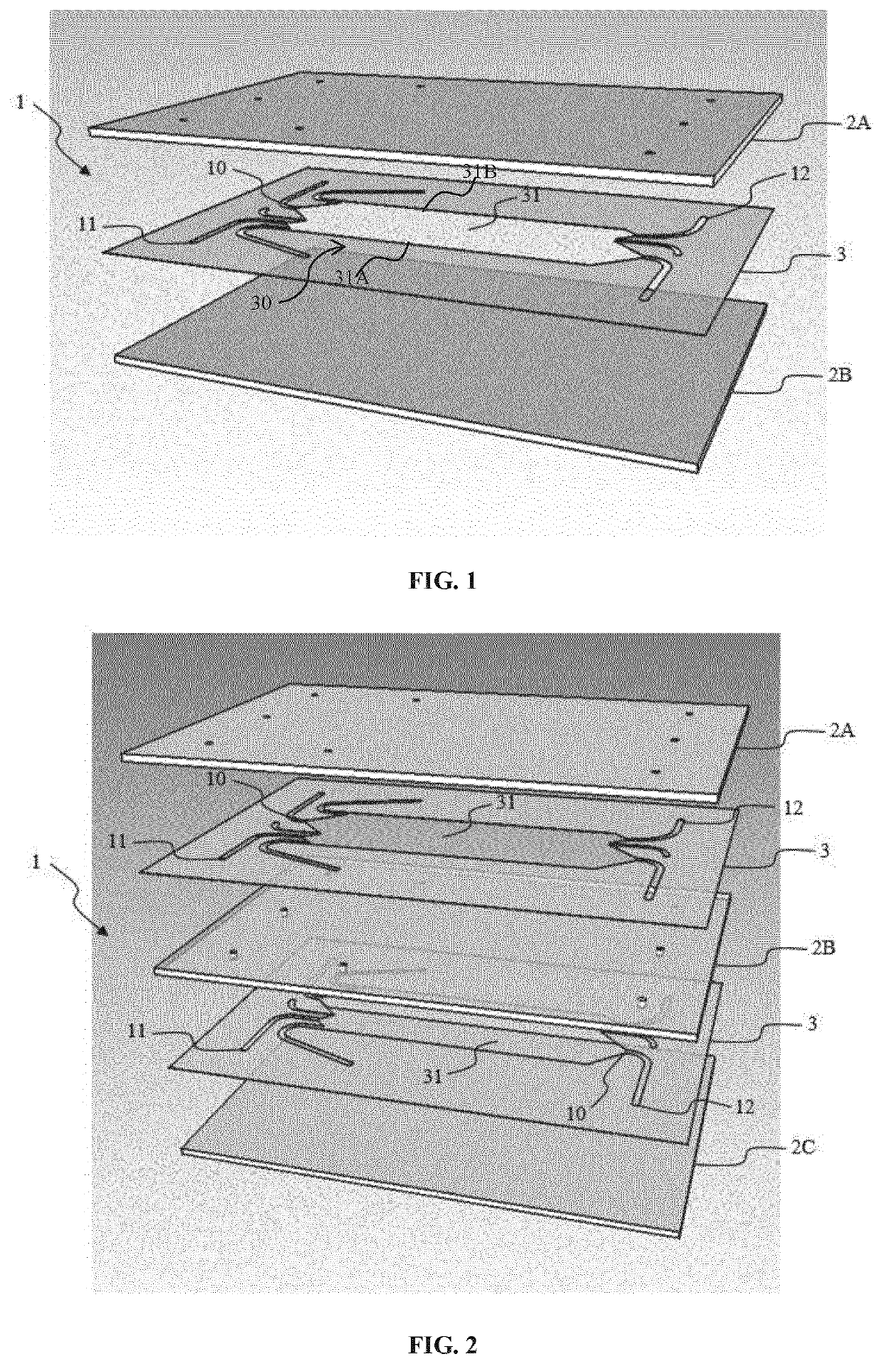
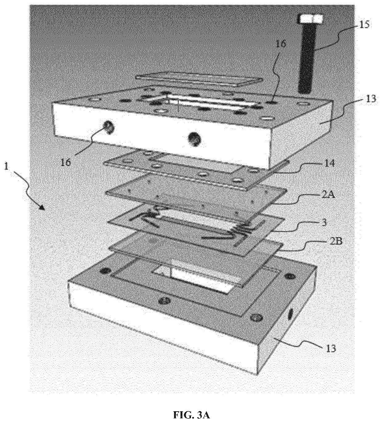
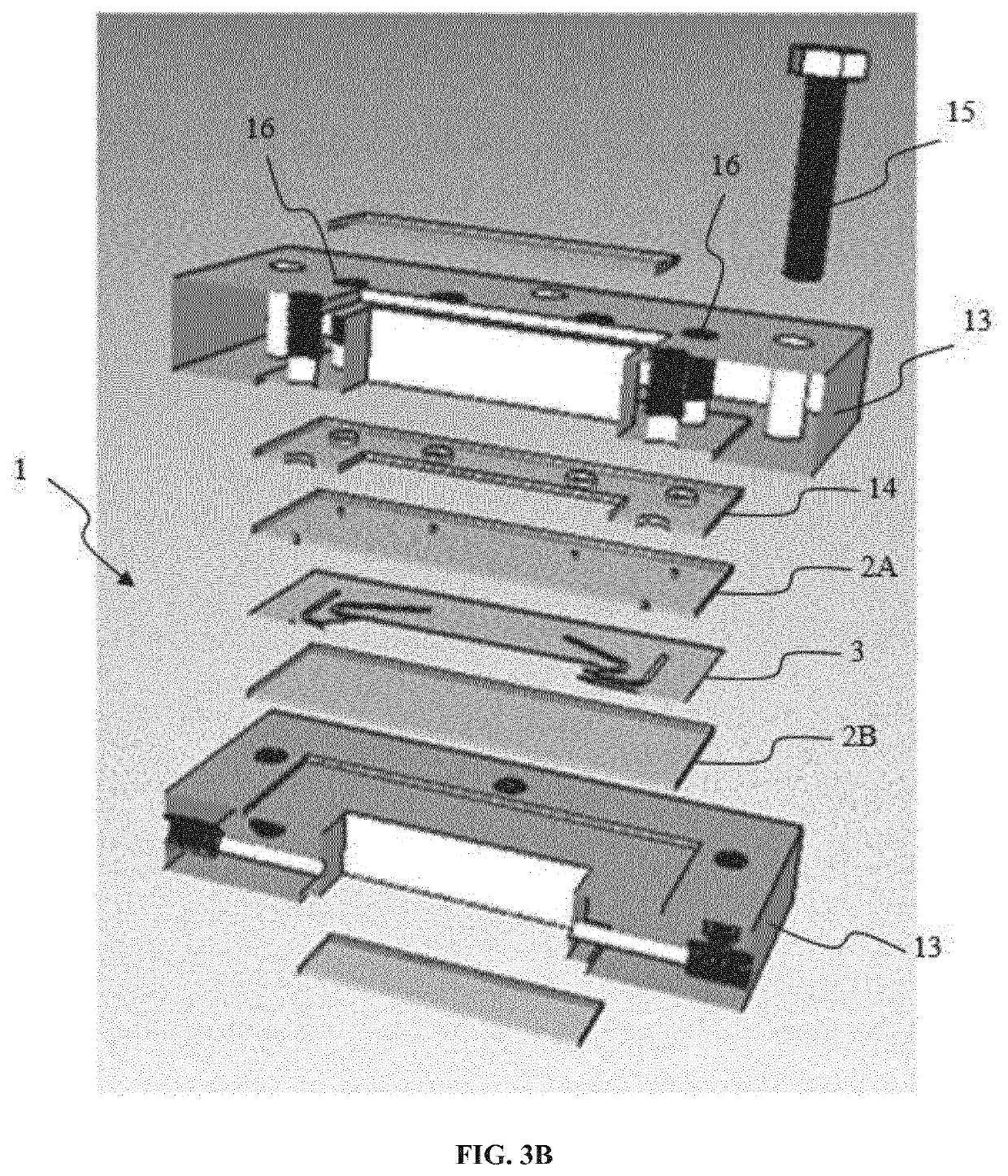
The present invention relates to a Micro-Free Flow Electrophoresis chip for analyzing or separating a sample including a pile (1) comprising at least two plates (2A, 2B), a sheet (3) uniformly disposed between the two plates (2A, 2B), clamping means, each sheet (3) comprising at least two inlets (11) for entry and at least one outlet (12) for exit of a first fluid electrode and a second fluid electrode, the first and second fluid electrodes applying an electric field to a separation chamber (31).

Description

FIELD OF INVENTION[0001]This invention relates to the field of free flow electrophoresis (FFE) and to analytical and (micro-)preparative methods and devices for the separation of chemical or biological entities.BACKGROUND OF THE INVENTION[0002]Free-Flow electrophoresis (FFE) is a free flow separation method: indeed, it works without any stationary phase. FFE has a longstanding position among analytical and (micro-)preparative methods in biochemistry and chemistry for the separation of, e.g., organic and inorganic compounds, peptides, macromolecules, organelles, cells and other particles or biological or chemical entities. It can be used in different modes such as zone electrophoresis, isoelectro-focusing or isotachophoresis.[0003]Entities to be separated are introduced into a separation chamber in between two plates where an electric field is applied in a transverse manner, usually perpendicular to the flow. According to their charge to size ratio and media viscosity, the entities a...

Claims


Application Information

Patent Timeline
IPC IPC(8): G01N27/447
CPCG01N27/44769G01N27/44791
Inventor DELMARCELLE, MICHAËLSTEFANIC, PATRICKJORIS, BERNARDLECOMTE, EDITH
Owner UNIV LIEGE
Learn More