Dielectric barrier discharge ionization detector

Active Publication Date: 2020-07-23
SHIMADZU CORP +1
View PDF0 Cites 0 Cited by
  • Summary
  • Abstract
  • Description
  • Claims
  • Application Information

AI Technical Summary

Benefits of technology

The present invention aims to solve the problem of creeping discharge in a dielectric pipe and prevent the detector from increasing in size. By periodically changing the potential difference between the electrodes attached to the outer wall of the dielectric pipe, the potential difference between the end of the pipe and the connection part is reduced, resulting in less likelihood of creeping discharge and without the need to increase the distance between the electrodes. This approach eliminates the need for additional components and keeps the detector's size compact.

Problems solved by technology

When creeping discharge occurs and the discharge range reaches the connection part of the dielectric pipe, the resulting discharge becomes unstable and the SN ratio is deteriorated.
However, in that case, the entire detector tends to increase in size, and it is difficult to reduce the size of the detector.
In addition, when the distance between the end of the dielectric and the discharge electrode is increased, the distance from the position where the discharge is generated to the charge collection part is increased, and the light from the plasma is difficult to reach the sample component.
Therefore, high detection sensitivity cannot be obtained.

Method used


Image

  • Dielectric barrier discharge ionization detector
  • Dielectric barrier discharge ionization detector
  • Dielectric barrier discharge ionization detector

Examples


Embodiment Construction

[0016]Now, an embodiment of a BID will be described below with reference to the drawings. The embodiment described below is merely an example of a configuration for realizing the present invention, and the present invention is not limited to this.

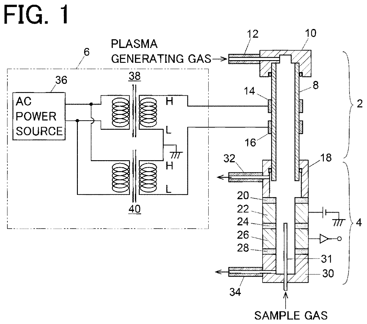
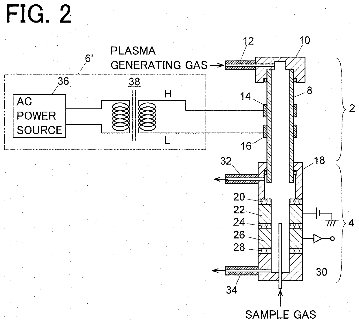
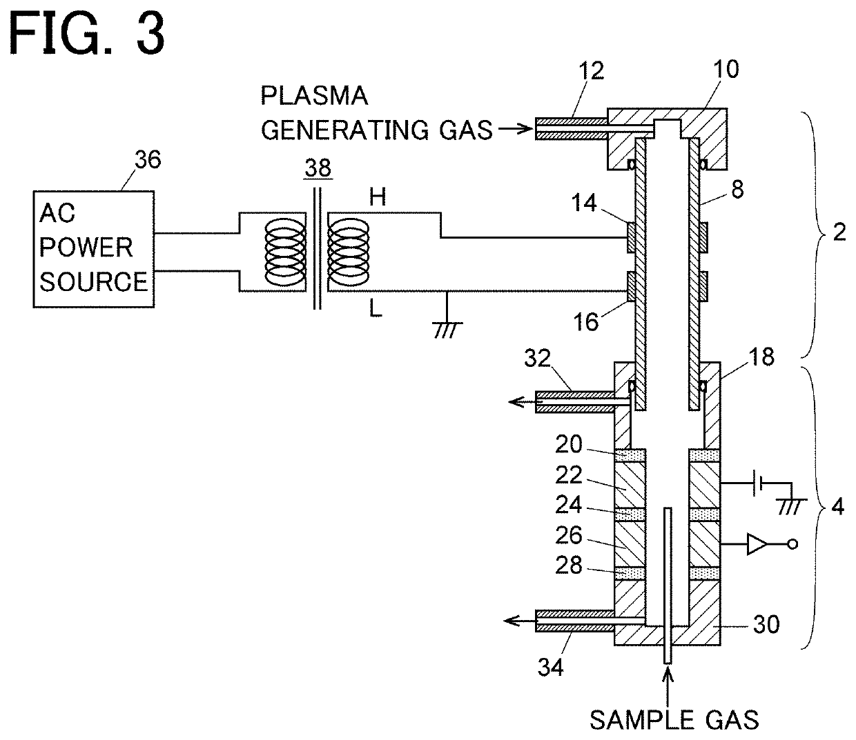
[0017]FIG. 1 shows an example of a BID. The BID of this example mainly includes a discharger 2, a detection section 4, and a voltage supply 6. The discharger 2 generates plasma due to dielectric barrier discharge, ionizes components in sample gas in the detection section 4 by excitation light emitted from the plasma, and detects the generated ions by collecting them using a collection electrode 26 provided in the detection section 4.

[0018]The discharger 2 includes a dielectric pipe 8 made of a dielectric such as quartz glass. A pair of electrodes 14 and 16 are attached to the outer wall of the dielectric pipe 8, and a connection member 10 is attached to a first end (upper end in the figure) of the dielectric pipe 8. The pair of electrodes 1...


PUM


Abstract

A BID includes: a discharger (2) including a dielectric pipe (8) and a pair of electrodes (14, 16) attached on an outer wall of the dielectric pipe, the pair of electrodes (14, 16) being arranged at a distance from each other in a direction along a central axis of the dielectric pipe (8), the discharger (2) being arranged so that plasma generating gas is introduced from a first end of the dielectric pipe (8) and configured to generates dielectric barrier discharge inside the dielectric pipe (8) to generate plasma; a detection section (4) including a sample gas introduction section (31) and a collection electrode (26) for collecting ions, the detection section (4) being configured to ionize components in the sample gas using light emitted from the plasma generated in the discharger (2) and to detect the generated ions by collecting them using the collection electrode (26); and a voltage supply (6; 6′) for generating a potential difference between the pair of electrodes (14, 16).

Description

BACKGROUND OF THE INVENTION1. Field of the Invention[0001]The present invention relates to a dielectric barrier discharge ionization detector.2. Description of the Related Art[0002]As a detector for gas chromatography, a dielectric barrier discharge ionization detector (hereinafter referred to as BID) using ionization by dielectric barrier discharge plasma has been put into practical use (see JP 2018-040718 A). The BID uses dielectric barrier discharge whose electrode surface is covered with a dielectric, so that it emits less thermoelectrons and secondary electrons than when using a metal electrode. Further, the BID generates non-equilibrium plasma with very low neutral gas temperature (almost no heat generation) by a low-frequency high-pressure power source to suppress generation of impurity gas due to heating of an inner wall material and achieve a highly stable discharge state, thereby being capable of realizing a high SN ratio.[0003]The BID disclosed in Patent Document 1 is rou...

Claims


Application Information

Patent Timeline
IPC IPC(8): H05H1/24G01N30/64
CPCG01N30/64G01N2030/642H05H2001/2456H05H1/2406G01N2030/025H05H1/2465H05H1/246
Inventor SHINADA, KEIKITANO
Owner SHIMADZU CORP
Why Eureka
Try Eureka