Transmittance-Variable Device
a transmission variable and transmission angle technology, applied in the field can solve the problems of shifted viewing angle characteristics in the vertical direction, poor transmission angle characteristics of transmission variable devices, etc., and achieve the effects of high transmittance, high shielding rate, and high contrast ratio
- Summary
- Abstract
- Description
- Claims
- Application Information
AI Technical Summary
Benefits of technology
Problems solved by technology
Method used
Image
Examples
example 1
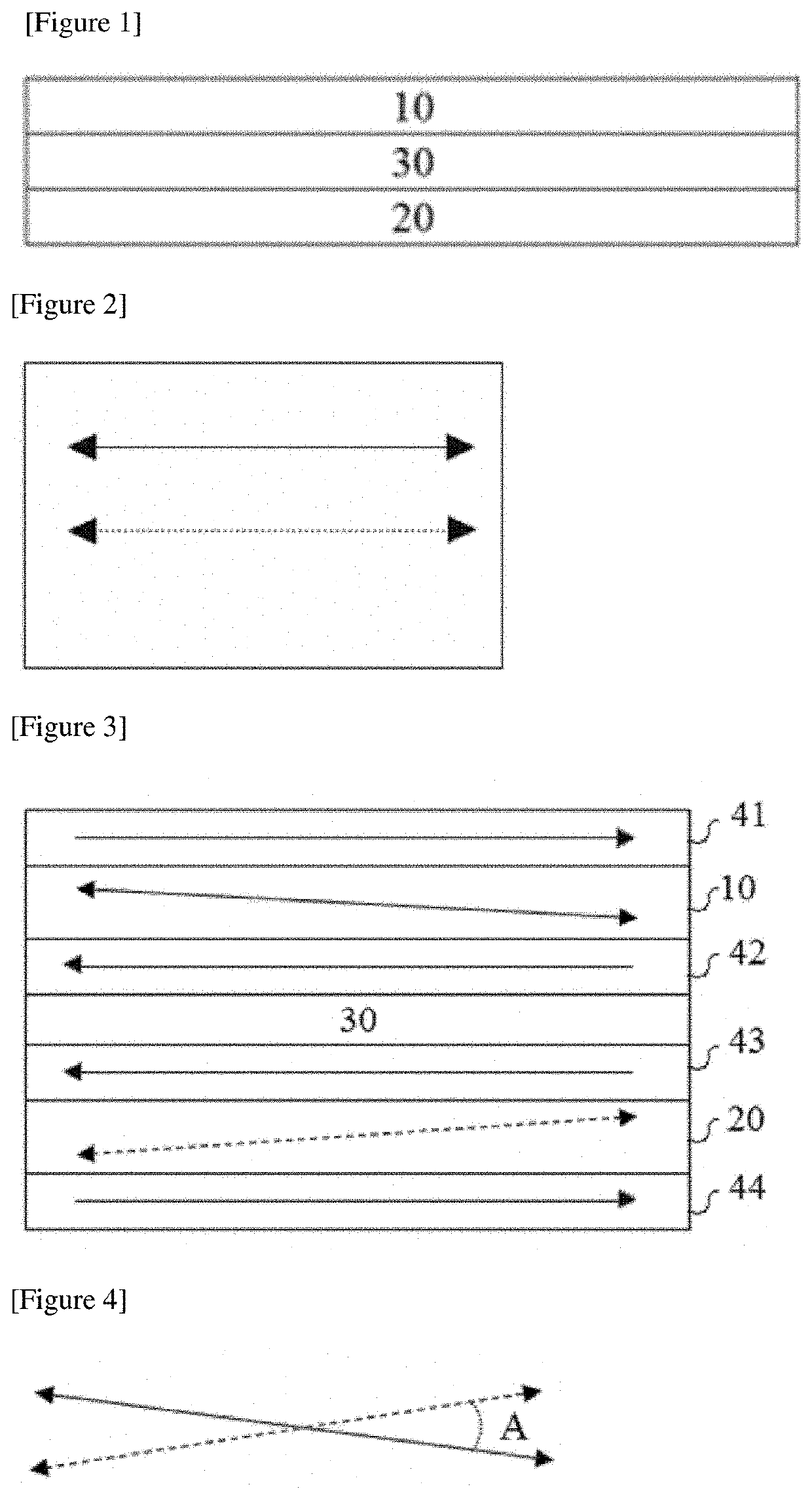
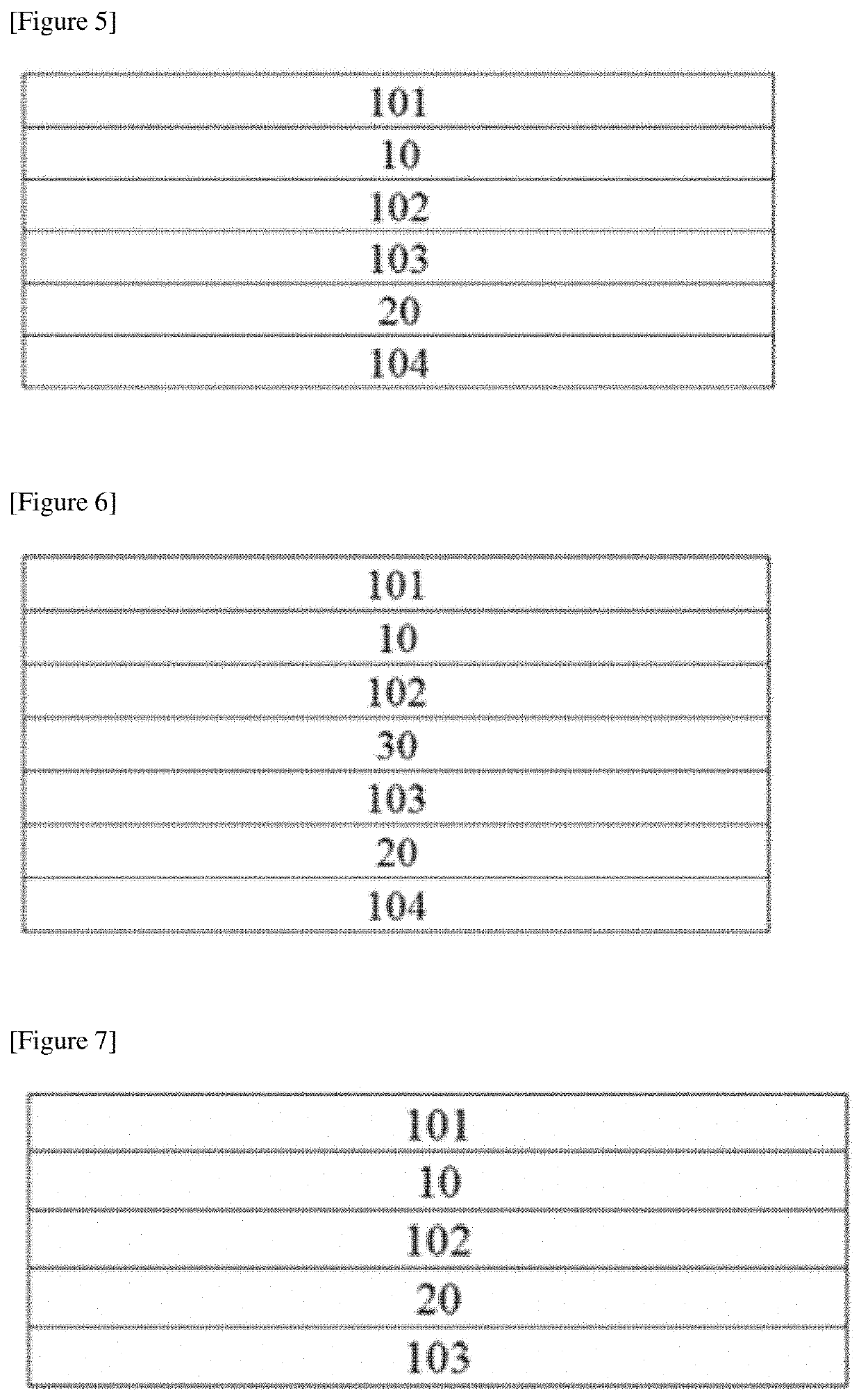
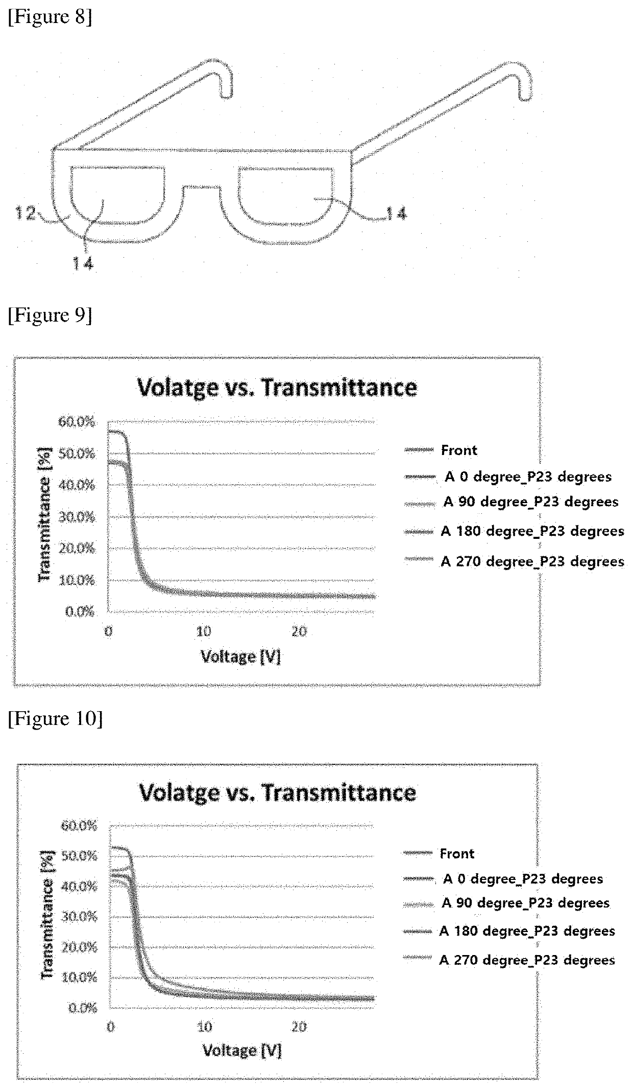
[0122]A first GH cell was produced by forming a GH layer between two COP (cycloolefin polymer) films in which an ITO (indium tin oxide) electrode layer and a vertical alignment film were sequentially formed on the surface. Here, the cell gap of the GH cell was set to about 12 μm. Here, as the vertical alignment film, an alignment film having a pretilt angle of about 89 degrees was used. The alignment film was formed to a thickness of about 200 nm by coating a polyimide-based vertical alignment film on the ITO electrode layer by bar coating, holding the film at 130° C. for about 30 minutes and then rubbing the film with a rubbing cloth. At this time, the two COP films were laminated so that the rubbing directions of the alignment films on the films were opposite to each other. Also, the GH layer was formed by applying a GH mixture in which nematic liquid crystals having dielectric constant anisotropy of about −4.9 and refractive index anisotropy of about 0.132 as a liquid crystal com...
example 2
[0123]A transmittance-variable element was manufactured in the same manner as in Example 1, except that as the phase difference element (30 in FIG. 3) introduced between the first and second GH cells, a laminated film of a COP (cycloolefin polymer) film having a plane phase difference of about 275 nm for a wavelength of 550 nm and having a flat wavelength characteristic and Nz (=(nx−nz) / (nx−ny), wherein nx is a refractive index in the slow axis direction, ny is a refractive index in the fast axis direction, and nz is a refractive index in the thickness direction) of about 1.2 and a vertical alignment liquid crystal layer having a thickness direction phase difference (Rth=dx(nz−ny)) in a range of about 180 to 200 nm was placed.
example 3
[0124]A transmittance-variable element was manufactured in the same manner as in Example 1, except that as the phase difference element (30 in FIG. 3) introduced between the first and second GH cells, a laminated film of a COP (cycloolefin polymer) film from having a plane phase difference of about 275 nm for a wavelength of 550 nm and having a reverse wavelength characteristic and a ratio (Re (450) / Re (550)) of a plane phase difference (Re (450)) for light with a wavelength of 450 nm to a plane phase difference (Re (550)) for light with a wavelength of 550 nm of about 0.8 or so and a vertical alignment liquid crystal layer having a thickness direction phase difference (Rth=dx(nz−ny)) of about 100 nm or so was placed.
PUM
| Property | Measurement | Unit |
|---|---|---|
| pretilt angle | aaaaa | aaaaa |
| thickness | aaaaa | aaaaa |
| wavelength | aaaaa | aaaaa |
Abstract
Description
Claims
Application Information
 - R&D
- Intellectual Property
- Life Sciences
- Materials
- Tech Scout
- Unparalleled Data Quality
- Higher Quality Content
- 60% Fewer Hallucinations
Browse by: Latest US Patents, China's latest patents, Technical Efficacy Thesaurus, Application Domain, Technology Topic, Popular Technical Reports.
© 2025 PatSnap. All rights reserved.Legal|Privacy policy|Modern Slavery Act Transparency Statement|Sitemap|About US| Contact US: help@patsnap.com


