MEMS device with optimized geometry for reducing the offset due to the radiometric effect

Active Publication Date: 2020-07-09
STMICROELECTRONICS SRL
View PDF0 Cites 4 Cited by
  • Summary
  • Abstract
  • Description
  • Claims
  • Application Information

AI Technical Summary

Benefits of technology

This patent text tracks a type of MEMS device that reduces errors caused by changes in light levels. The device has a specific structure called a "teeter-totter" which has a suspended mass that moves in opposite directions when the device is tilted. This helps to accurately measure the device's movement and correct for any errors that might occur due to light levels. Overall, this patent provides a way to improve the accuracy of inertial sensors that measure movement.

Problems solved by technology

In general, non-uniform temperature distributions within a MEMS device of the above type have various grounds.
In fact, In some situations, for example at turning-on of the device, fast temperature variations may lead to a non-uniform distribution within the die, as represented in FIG. 2.
The problem of the radiometric forces acting on a mobile mass (having a flat shape) of a MEMS device has so far not been tackled very much.

Method used


Image

  • MEMS device with optimized geometry for reducing the offset due to the radiometric effect
  • MEMS device with optimized geometry for reducing the offset due to the radiometric effect
  • MEMS device with optimized geometry for reducing the offset due to the radiometric effect

Examples


Embodiment Construction

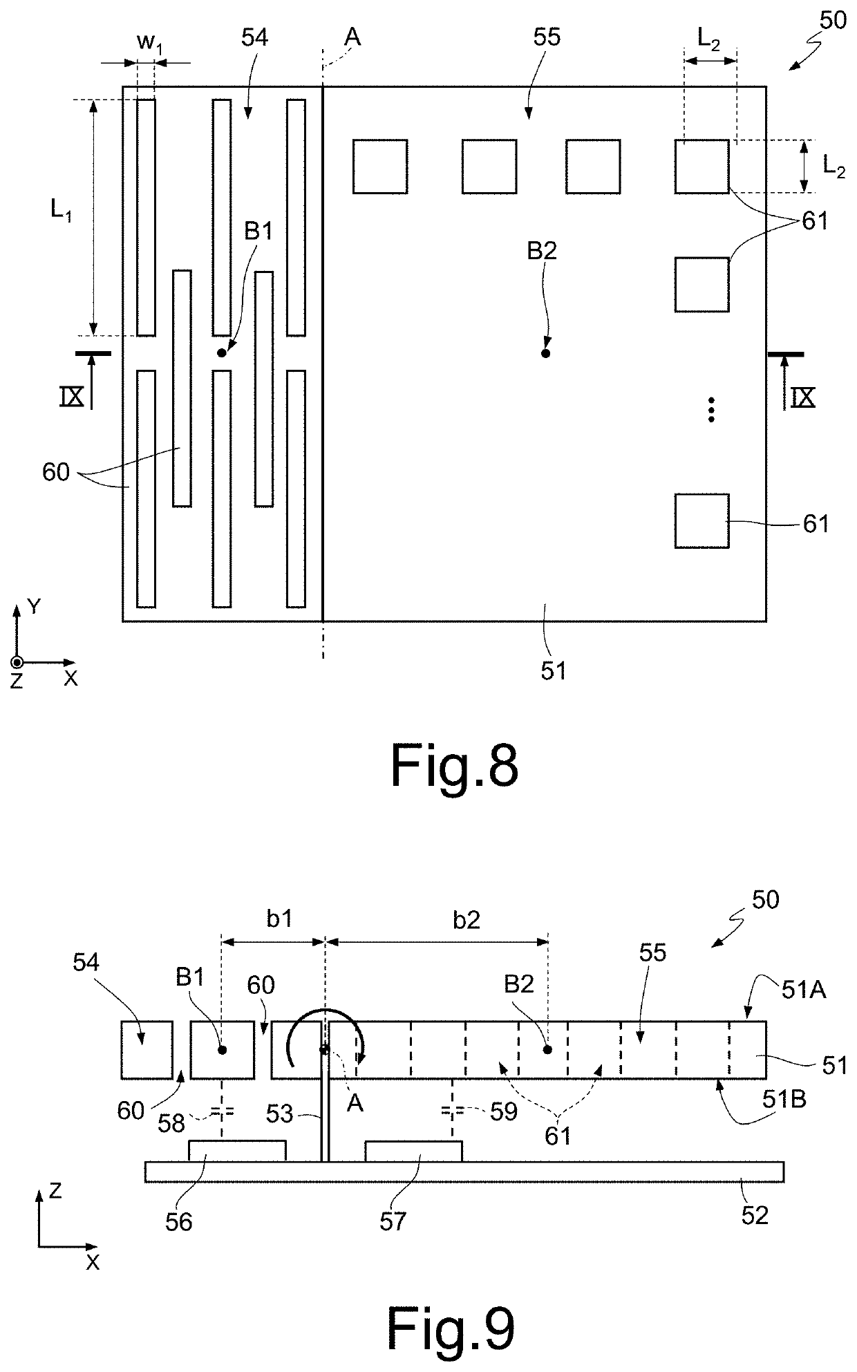
[0047]FIGS. 8 and 9 are schematic illustrations of a sensor 50 of an inertial type having a so-called “teeter-totter” structure.

[0048]In detail, the sensor 50 comprises a mobile mass 51 suspended over a substrate 52 (FIG. 9) through a pillar 53, which extends from the substrate 52 parallel to axis Z of a Cartesian reference system XYZ. The pillar 53 is coupled to the mobile mass 51 through hinges and springs (not shown), which enable tilting of the mobile mass 51 about a rotation axis A.

[0049]The mobile mass 51 has a characteristic quantity (here the length in direction X) much greater than its thickness, for example ten times greater. In particular, at rest, the mobile mass 51 has main surfaces (top surface 51A and bottom surface 51B) extending in a plane parallel to plane XY of the Cartesian reference system XYZ and a thickness tp extending parallel to axis Z. The thickness tp of the mobile mass 51 is uniform over its entire area, as may be seen in FIG. 9. In the shown example, th...


PUM


Abstract

A MEMS device with teeter-totter structure includes a mobile mass having an area in a plane and a thickness in a direction perpendicular to the plane. The mobile mass is tiltable about a rotation axis extending parallel to the plane and formed by a first and by a second half-masses arranged on opposite sides of the rotation axis. The first and the second masses have a first and a second centroid, respectively, arranged at a first and a second distance b1, b2, respectively, from the rotation axis. First through openings are formed in the first half-mass and, together with the first half-mass, have a first total perimeter p1 in the plane. Second through openings are formed in the second half-mass and, together with the second half-mass, have a second total perimeter p2 in the plane, where the first and the second perimeters p1, p2 satisfy the equation: p1×b1=p2×b2.

Description

BACKGROUNDTechnical Field[0001]The present disclosure relates to a MEMS device. In particular, the present disclosure relates to a MEMS (Micro-Electro-Mechanical System) inertial sensor, such as an accelerometer or a gyroscopeDescription of the Related Art[0002]As is known, the use of MEMS devices of the above type is progressively increasing in ever-wider technical fields, due to their capacity of supplying accurate signals, their low cost, and their high versatility.[0003]In particular, inertial sensors of the above type are progressively used in consumer applications and in the automotive field, for example for indoor navigation and as aids to autonomous driving, i.e., applications where it is important to have a high precision and provide outputs as stable as possible also when the environmental and / or internal parameters vary. In particular, in these applications, it is desirable for the output signals of the device to be stable in temperature, both with respect to external eff...

Claims


Application Information

Patent Timeline
IPC IPC(8): B81B7/00G01P15/02G01C19/5712
CPCB81B2201/0242B81B2203/04G01P15/02B81B2201/0235G01C19/5712B81B2203/0118B81B7/0019B81B2207/012B81B2203/058B81B7/02B81B5/00B81B2201/0228G01P15/125G01P2015/0831G01P15/08
Inventor RIZZINI, FRANCESCOTOCCHIO, ALESSANDRO
Owner STMICROELECTRONICS SRL
Why Eureka
Try Eureka