
Roller assembly, casting apparatus, and roller separating method for same

a technology of rolling assembly and casting apparatus, which is applied in the field of rolling assembly, casting apparatus, and rolling separation method for the same, can solve the problems of difficult to separate the segment to recover equipment, frequent damage to the hydraulic cylinder segments according to related arts, etc., and achieves the effect of reducing the time and manpower required to recover equipment, easy and fast separation, and easy separation from the slab

Active Publication Date: 2020-07-09
POHANG IRON & STEEL CO LTD
View PDF0 Cites 0 Cited by
  • Summary
  • Abstract
  • Description
  • Claims
  • Application Information

AI Technical Summary

Benefits of technology

The patent text describes a method for easily retreating rollers in continuous casting equipment, using a plunger structure to cause the rollers to retreat when there is a situation like outflow of molten steel or retention of slabs. This allows for quick separation of slabs and equipment, reducing the time and effort required to recover the equipment. The technical effect of this invention is improved efficiency and flexibility in continuous casting equipment.

Problems solved by technology

The segments having the hydraulic cylinder according to related arts are frequently damaged due to high-temperature and high-humidity operation environments and high ferro-static pressure inside the slab.
At this point, when the thickness of the slab is large, it is impossible to cut the slab, and the segment should be separately removed, but in the above-described emergent situation, most rollers are fused to the slab, and therefore it is difficult to separate the segment to recover the equipment and deal with the emergent situation.

Method used


Image

  • Roller assembly, casting apparatus, and roller separating method for same
  • Roller assembly, casting apparatus, and roller separating method for same
  • Roller assembly, casting apparatus, and roller separating method for same

Examples


Embodiment Construction

[0031]Hereinafter, embodiments of the present invention will be described in detail with reference to the accompanying drawings. The present invention may, however, be embodied in different forms and should not be construed as limited to the embodiments set forth herein. Rather, these embodiments are provided so that this disclosure will be thorough and complete, and will fully convey the scope of the inventive concept to those skilled in the art. To describe exemplary embodiments, drawings may be exaggerated and like reference numerals denote like elements in the drawings.

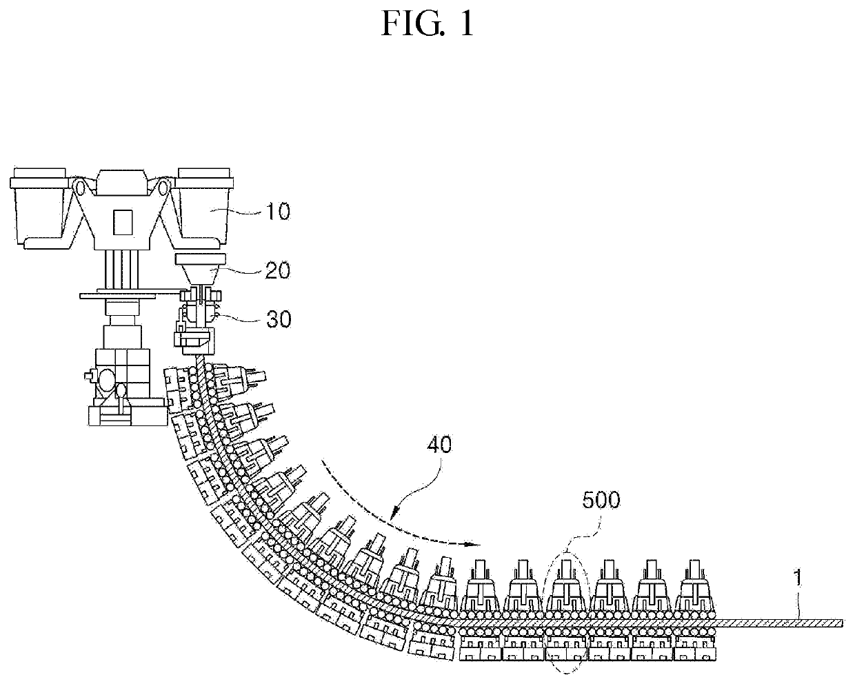
[0032]FIG. 1 is a schematic view of a casting apparatus in accordance with an exemplary embodiment.

[0033]Referring to FIG. 1, a casting apparatus in accordance with an exemplary embodiment will be described. A casting apparatus in accordance with an exemplary embodiment is a casting apparatus that casts a to-be-treated material such as a slab 1 by using a mold 30 and includes a plurality of segments 500 consecutiv...


PUM

PropertyMeasurementUnit
stretchableaaaaaaaaaa
hydraulic pressureaaaaaaaaaa
inner diameteraaaaaaaaaa

Abstract

Provided is a roller assembly which includes: a supporter configured to rotatably support a roller disposed in a movement path of a to-be-treated material; a fixed shaft attached to a rear surface of the supporter and having at least a stretchable portion; a body attached to the rear surface side of the supporter so as to surround the fixed shaft; and a plunger attached so as to connect the body and the fixed shaft and formed so that at least a portion thereof advances and retreats with respect to the movement path, a casting device provided with the roller assembly, and a roller separating method, wherein the roller assembly is capable of separating the roller from the movement path during emergency.

Description

CROSS-REFERENCE TO RELATED APPLICATIONS[0001]This application is a national entry of PCT Application No. PCT / KR2018 / 009039 filed on Aug. 8, 2018, which claims priority to and the benefit of Korean Application No. 10-2017-0101208 filed Aug. 9, 2017, in the Korean Patent Office, the entire contents of which are incorporated herein by reference.TECHNICAL FIELD[0002]The present disclosure relates to a roller assembly, a casting apparatus, and a roller separating method for the same, and more particularly, to a roller assembly in which rollers are retreatable from the movement path of a to-be-treated material, a casting apparatus in which a roller fused to a slab on the movement path is separable during emergency, and a roller separating method for the casting apparatus.BACKGROUND ART[0003]Continuous casting equipment is the equipment for producing slabs using molten steel, and is configured by a turndish for storing a molten steel, a mold for receiving the molten steel in the turndish a...

Claims


Application Information

Patent Timeline
Patent Type & Authority Applications(United States)
IPC IPC(8): B22D11/128
CPCB22D11/1282B22D11/1287B22D11/128B22D11/208B22D11/1285
Inventor OH, KYUNG SHIKKANG, YOUNG HOONLEE, JOO DONGJOUNG, KI HWAN
Owner POHANG IRON & STEEL CO LTD
Learn More