Piston rod brake mechanism

a technology of a brake mechanism and a piston rod, which is applied in the direction of intravenous devices, other medical devices, syringes, etc., can solve the problems of difficult to distinguish the clicks produced during the first 3-5 expelled units, difficult to precisely detect electronic devices, and high cost, so as to eliminate or reduce at least one drawback

Active Publication Date: 2020-07-02
NOVO NORDISK AS
View PDF0 Cites 0 Cited by
  • Summary
  • Abstract
  • Description
  • Claims
  • Application Information

AI Technical Summary

Benefits of technology

The invention is about a new injection device that makes it easier to detect the initial phase of a dose expelling action, which helps to determine the amount of drug being expelled more accurately. This is achieved by retarding the initial rotation of the piston rod structure, which results in more distributed and detectable outputs over the entire dose expelling action. The device can produce both tactile and auditory outputs, which users can count to determine the overall amount of drug being expelled. This design makes it easier for users to detect and control the injection process.

Problems solved by technology

However, in the initial phase of an insulin expelling action the spring driven components move very fast due to axial compression of resilient parts of the injection device, particularly the piston.
This means that the clicks produced during the first 3-5 expelled units can be difficult to distinguish.
In fact, even a precise electronic detection may be challenging.
While this issue may be more dominant within automatic injection devices it is indeed also relevant to manual injection devices, where it can be difficult for the user to control the speed of depression of the injection button in the initial phase of a dose expelling action.

Method used


Image

  • Piston rod brake mechanism
  • Piston rod brake mechanism
  • Piston rod brake mechanism

Examples


first embodiment

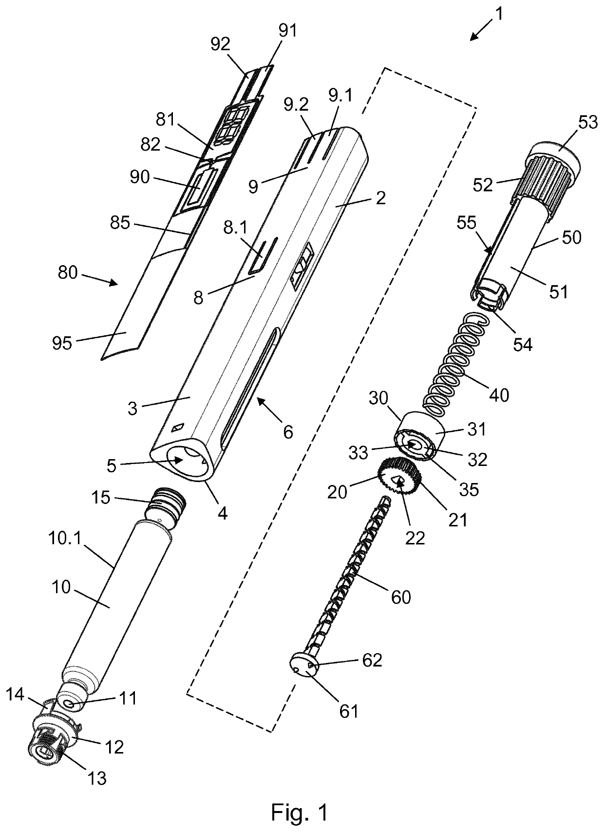
[0076]In the following the invention will be described in connection with a use of the pen injection device 1 according to the

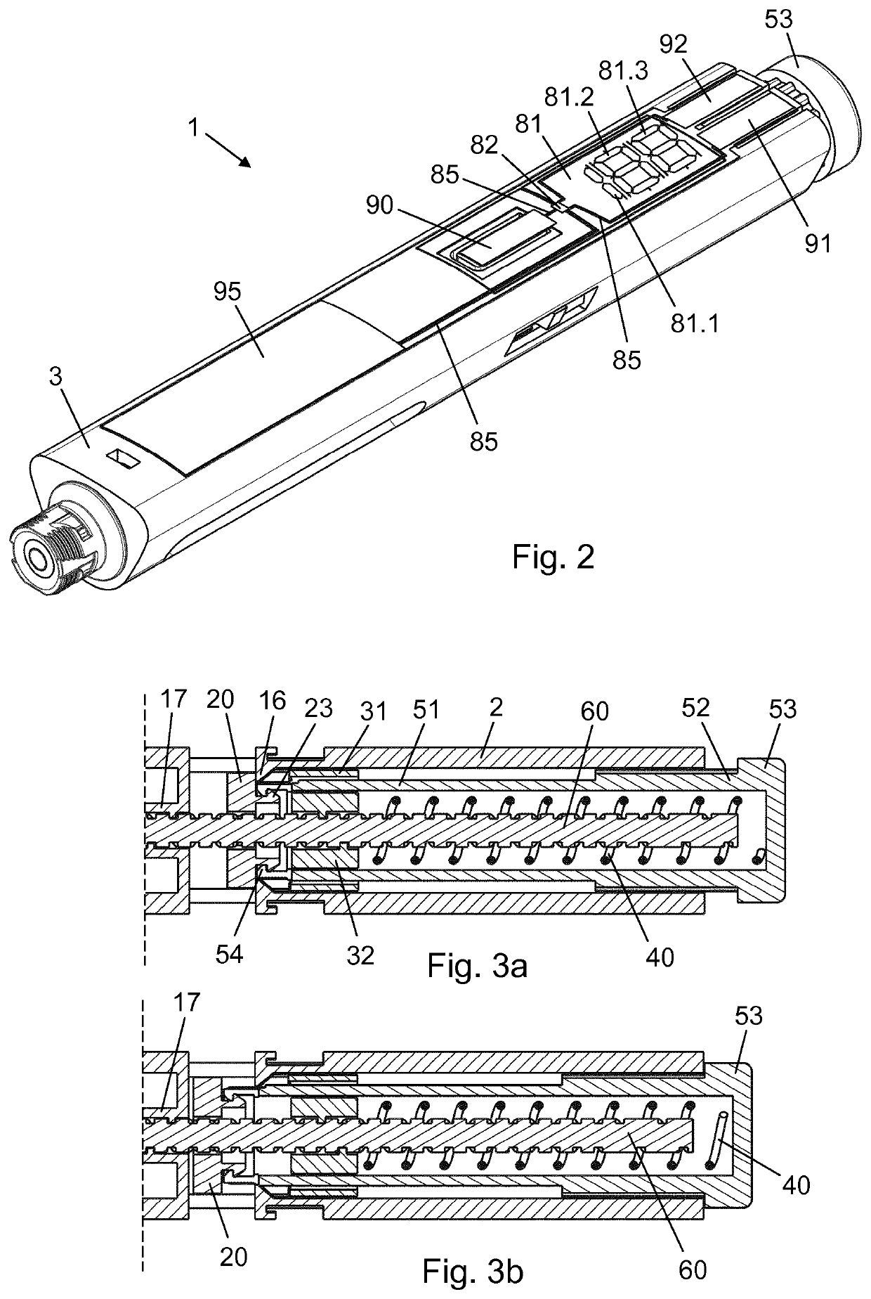
[0077]In FIG. 2 the pen injection device 1 is in the dose setting state, where the end button 53 is axially spaced apart from the housing 2. In this state a dose to be delivered from the cartridge 10 is set by the user rotating the end button 53 about the longitudinal axis.

[0078]The piston rod 60 comprises a first non-self-locking thread, which mates with a thread in the nut member 17 and an overlapping oppositely handed second non-self-locking thread which mates with a thread in the nut structure 32, providing a mechanical advantage of 2:1.

[0079]Due to the rotationally interlocked relationship between the setting nut 30 and the dose dial knob 50 the nut structure 32 will travel proximally along the second non-self-locking thread of the piston rod 60 when the end button 53 is rotated clockwise (seen from the proximal end of the pen injection device 1) in a di...

second embodiment

[0090]FIG. 9 is a longitudinal section view of a distal portion of a pen injection device according to another embodiment of the invention. Specifically, the figure shows a cartridge 110 with a cartridge body 110.1 accommodated in a housing 102. A piston rod 160 is configured to exert a pressure on and apply a torque to a piston 115 of the cartridge 110 via a two-component piston washer 161 (see FIG. 10) in order to expel a dose of drug contained in the cartridge 110. The pen injection device according to this second embodiment of the invention is principally and functionally similar to the previously disclosed pen injection device 1, only the rotational coupling between the piston 115 and the piston rod 160 differing from the previous solution.

[0091]The piston washer 161 comprises a rigid washer core 165 and a softer interface body 162, the latter providing both a distal end face 163 suited for interaction with the piston 115 and a lip 164 for mechanical connection with an interior...


PUM


Abstract

The invention provides a pen-type injection device (1) with a piston rod brake mechanism for improving the determination of an expelled dose.

Description

FIELD OF THE INVENTION[0001]The present invention relates to injection devices capable of expelling one or more doses of drug from a drug reservoir.BACKGROUND OF THE INVENTION[0002]In the diabetes care segment parenteral drug administration carried out using a traditional vial and syringe system is increasingly being substituted by administration using a pen injection device. Pen injection devices are particularly convenient in that they allow the user to perform a dosed injection from a prefilled drug reservoir without first having to manually transfer the particular dose from one reservoir (the vial) to another (the syringe).[0003]Predominantly, two types of pen injection devices are available, durable injection devices being capable of delivering one or more doses of drug from a prefilled drug cartridge which can be loaded into the device before use and replaced after exhaustion, and disposable injection devices being capable of delivering one or more doses of drug from a prefill...

Claims


Application Information

Patent Timeline
Patent Type & Authority Applications(United States)
IPC IPC(8): A61M5/315A61M5/20A61M5/24
CPCA61M2205/581A61M5/31568A61M5/31553A61M2205/50A61M2005/2444A61M5/31501A61M2205/0294A61M5/24A61M5/20A61M2205/502A61M2205/582A61M5/31515A61M5/31583A61M2005/2086A61M2005/3126
Inventor JAKOBSEN, NIKOLAJ EUSEBIUSHANSEN, STEFFEN
Owner NOVO NORDISK AS
Why Eureka
Try Eureka