Inertial hydrodynamic pump and wave engine
a hydrodynamic pump and wave engine technology, applied in the direction of energy supply, special-purpose vessels, vessel construction, etc., can solve the problems of reducing the pressure inside the uppermost, and achieve the effect of optimizing the harvesting of energy from ocean waves, long-lived, and high-reliability
- Summary
- Abstract
- Description
- Claims
- Application Information
AI Technical Summary
Benefits of technology
Problems solved by technology
Method used
Image
Examples
embodiment 100
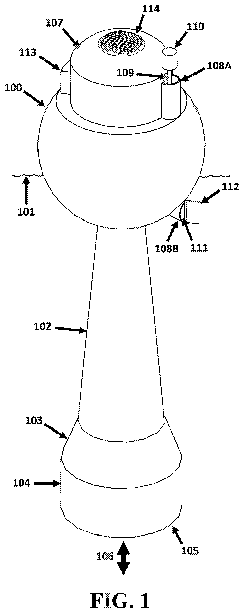
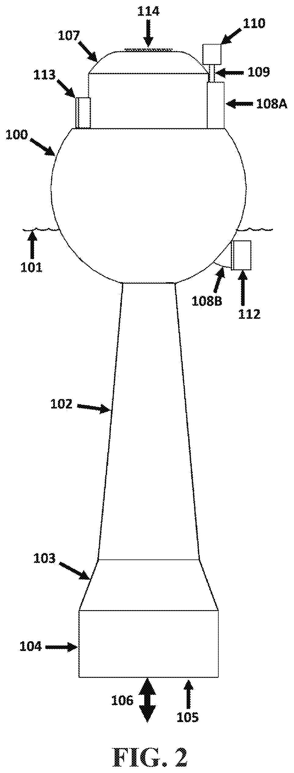
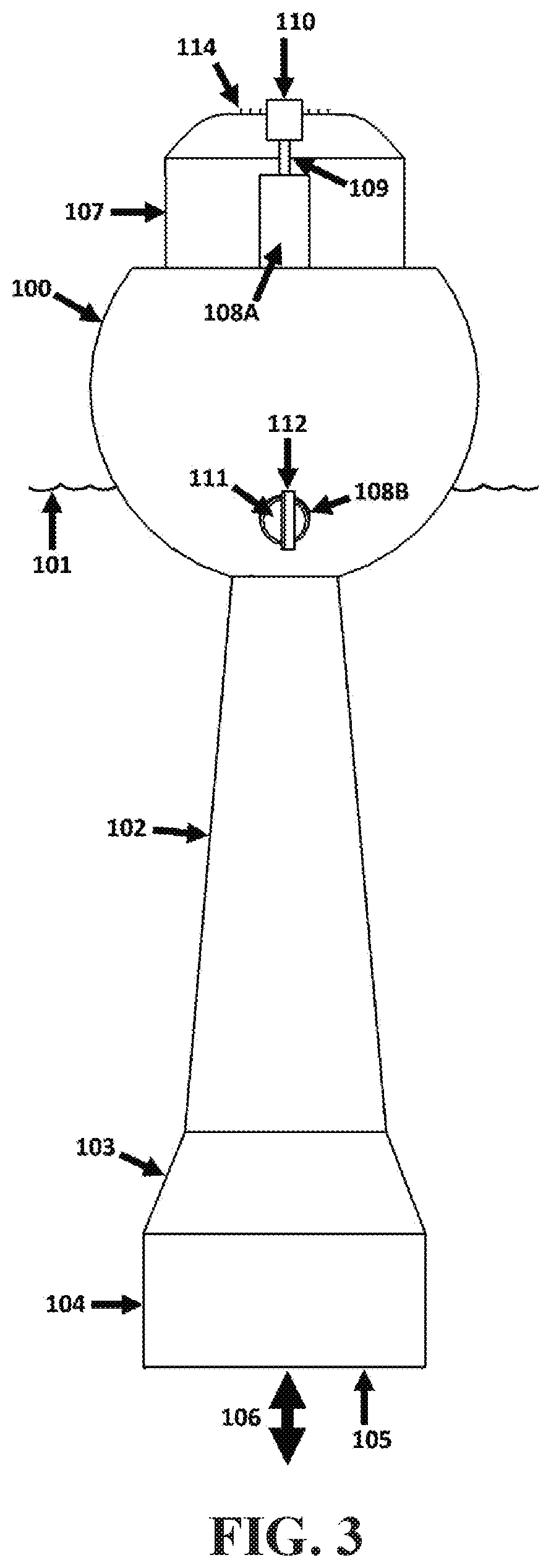
[0817]The buoyant embodiment 100 floats adjacent to an upper surface 101 of a body of water over which waves tend to pass. The embodiment incorporates a tapered inertial water tube 102-104 characterized by approximately circular cross-sections with respect to sectional planes normal to a (nominally vertical) longitudinal axis of the tube, and / or normal to an axis of inner-tube fluid flow, i.e., characterized by approximately “flow-normal cross-sectional shapes and / or areas”. An upper first portion 102 of the inertial water tube 102-104 has a frusto-conical shape (having circular flow-normal cross-sectional areas that increase in diameter with respect to increasing depths within the body of water 101 on which the embodiment floats). A second portion 103 of the inertial water tube 102-104 has a frusto-conical shape of a greater included angle. And, a bottom-most third portion 104 of the inertial water tube 102-104 is approximately cylindrical (having circular flow-normal cross-section...
embodiment 200
[0838]The buoyant embodiment 200 floats adjacent to an upper surface 201 of a body of water over which waves tend to pass. The embodiment incorporates an inertial water tube 202-203 comprised of both convex (e.g., 203) and concave (e.g., 202) tubular segments. A lower mouth 204 allows water to move 205 into and out from the interior of the inertial water tube 202-203. And, an upper mouth (not visible and inside the embodiment) of the inertial water tube 202-203 allows water to be ejected up and out of the inertial water tube, and into a water reservoir 206, when the water inside the inertial water tube rises fast enough and / or far enough. A portion of the gravitational potential energy and kinetic energy of the water ejected from the upper mouth of the inertial water tube 202-203 is preserved through the capture of a portion of that water in the water reservoir 206 which is positioned above the surface 201 of the body of water to which it will return.
[0839]A portion of the water tra...
embodiment 300
[0882]As the embodiment 300 moves up and down in response to waves traveling across the surface 301 of the body of water on which it floats, water within the embodiment's inertial water tube 302 tends to oscillate in a direction approximately parallel to a longitudinal axis of the inertial water tube, occasionally ejecting water from tubes (not visible) and upper mouths and / or apertures (not visible) incorporated within and / or at an upper end of the inertial water tube 302. Water ejected from the top of the inertial water tube 302 enters one of the four water reservoirs 305-308 at an approximately tangential orientation to each respective water reservoir's radially-symmetrical interior, thereby tending to induce in the water therein a swirling motion.
[0883]Water within each water reservoir 309-312 flows back to the body of water 301 through a respective effluent pipe e.g., 313 and 314, each effluent pipe of which is oriented so as to release and / or discharge its effluent in an appro...
PUM
 Abstract
Description
Claims
Application Information
 - R&D
- Intellectual Property
- Life Sciences
- Materials
- Tech Scout
- Unparalleled Data Quality
- Higher Quality Content
- 60% Fewer Hallucinations
Browse by: Latest US Patents, China's latest patents, Technical Efficacy Thesaurus, Application Domain, Technology Topic, Popular Technical Reports.
© 2025 PatSnap. All rights reserved.Legal|Privacy policy|Modern Slavery Act Transparency Statement|Sitemap|About US| Contact US: help@patsnap.com


