
Electronic device

Inactive Publication Date: 2020-05-21
INVENTEC PUDONG TECH CORPOARTION +1
View PDF8 Cites 0 Cited by
  • Summary
  • Abstract
  • Description
  • Claims
  • Application Information

AI Technical Summary

Benefits of technology

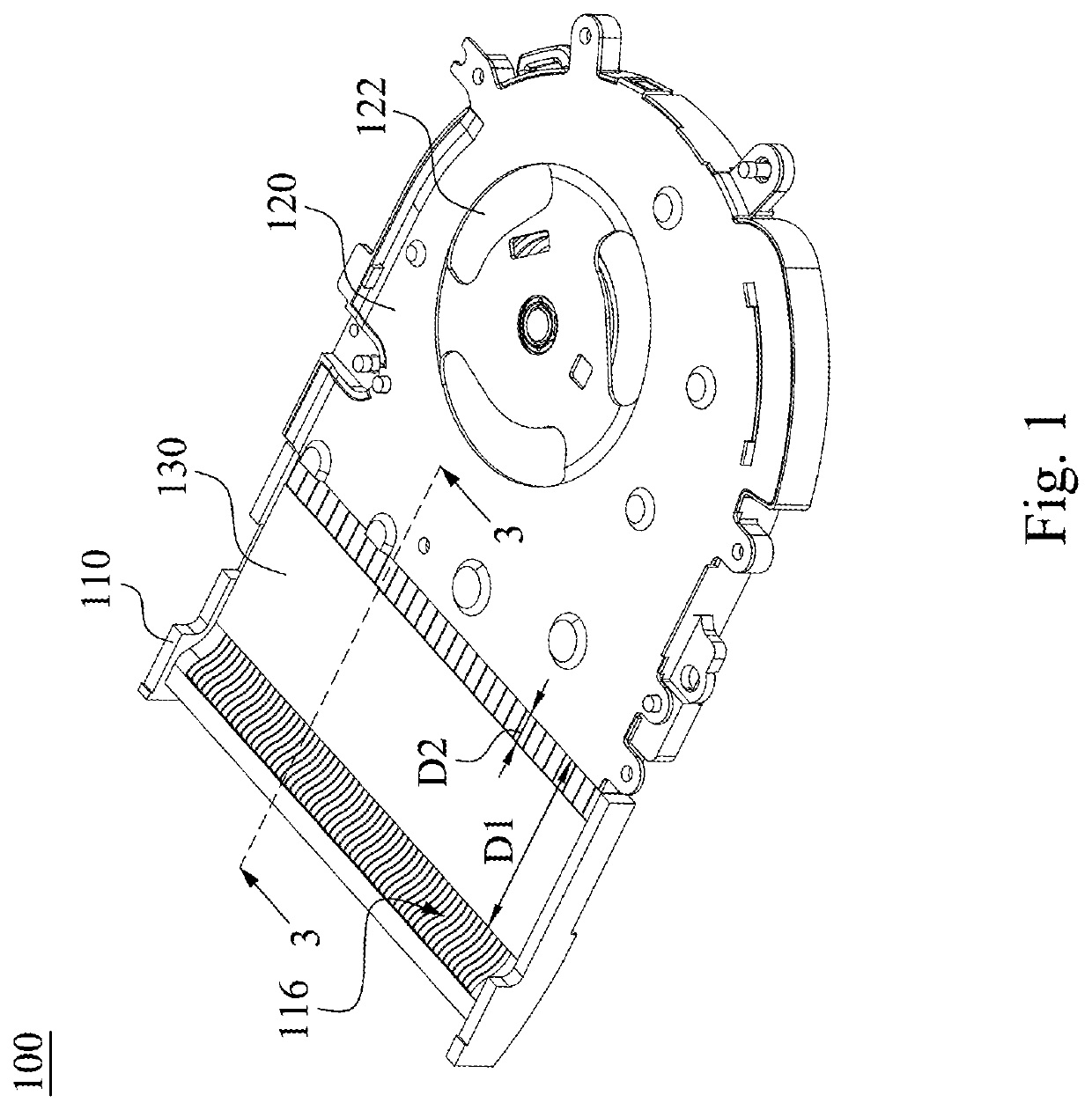
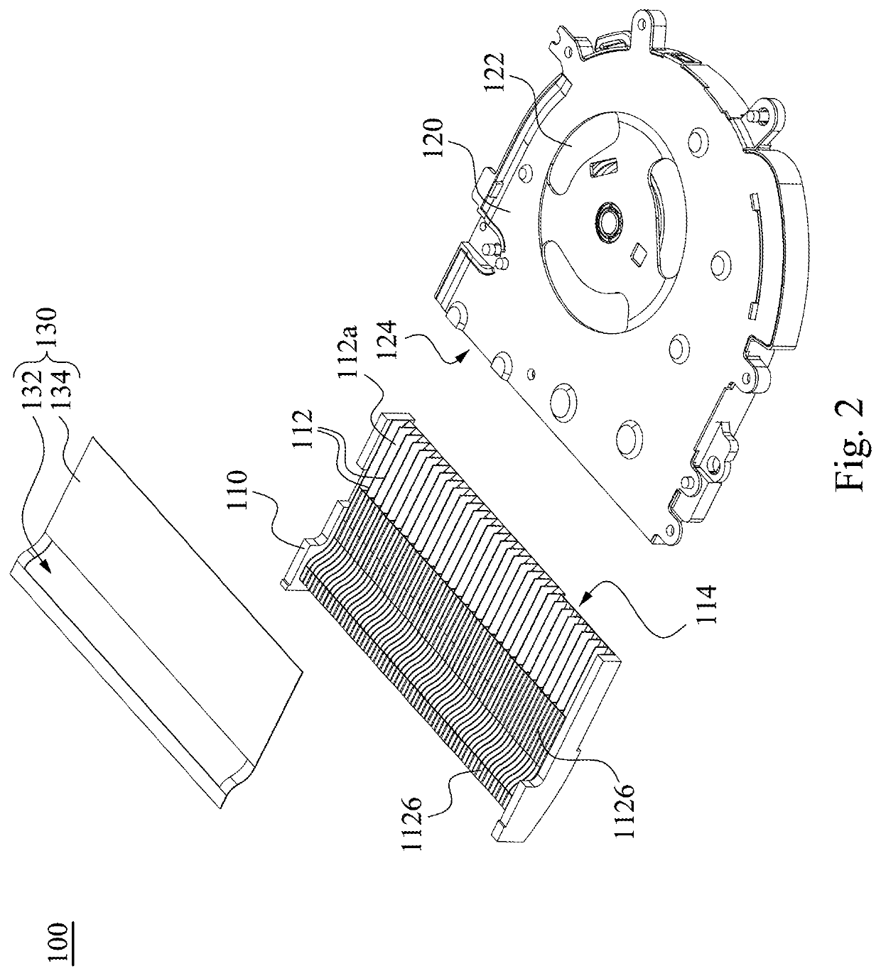
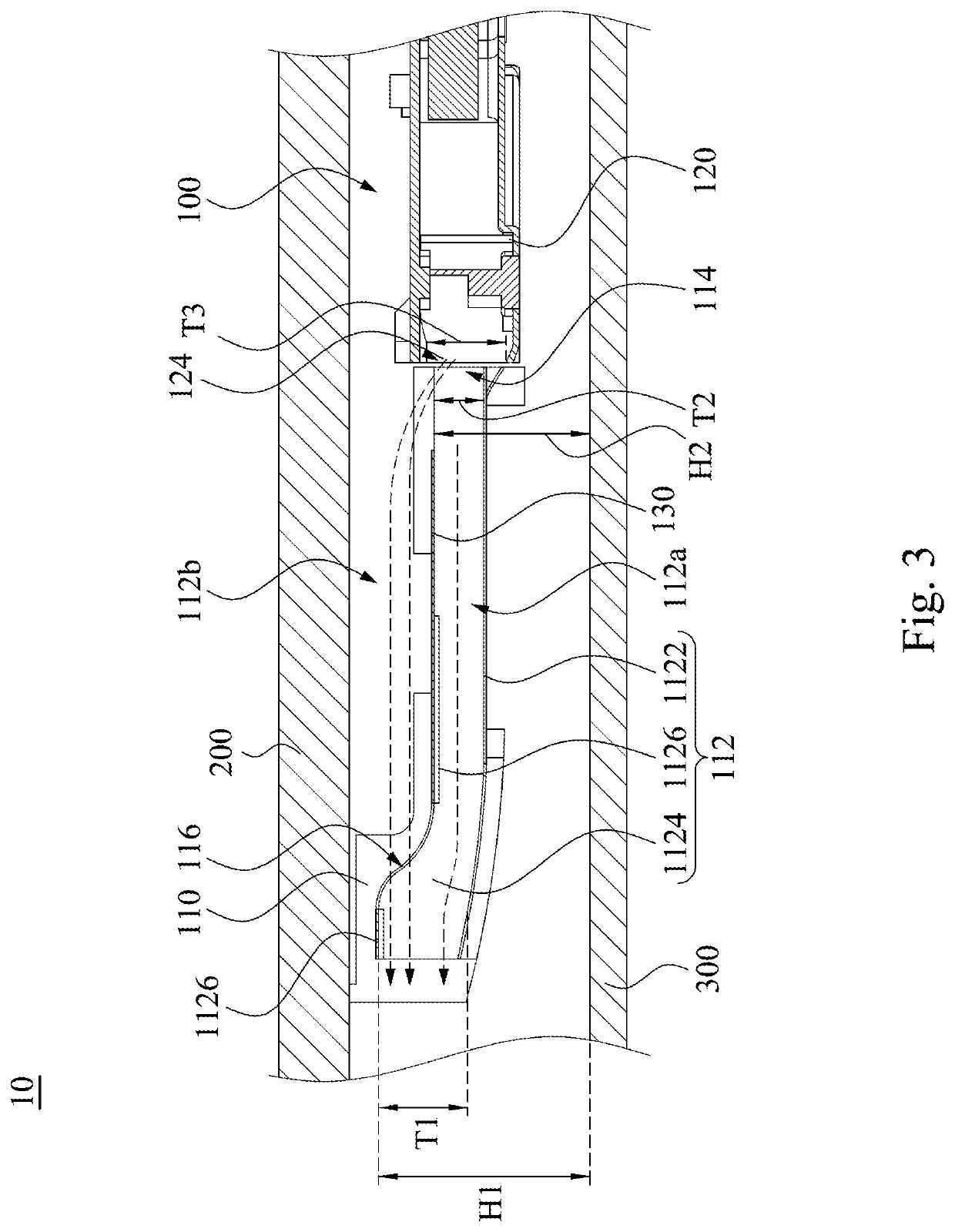
The electronic device described in this patent has a heat dissipation fin set with an isolation layer and an opening that acts as a second air inlet. This results in two air flows, one through the heat dissipation fin set to cool it, and another above it to cool the device chassis. After cooling the chassis, the air flow above the fin set recombines with it through the second air inlet, further improving heat dissipation performance. This configuration not only enhances the heat dissipation performance of the heat dissipation fin set, but also cools the user's chassis wall, improving their experience.

Problems solved by technology

With the heat dissipation module, the heat generated by the computing components or electronic components would not be accumulated in the electronic device which results in the raising temperature of the electronic device and the failure of the electronic device.
In severe cases, the heat accumulation in the electronic device may damage the components in the electronic device.
When the heat dissipation module becomes smaller, the heat dissipation performance of the heat dissipation module is deteriorated resulting in the raising temperature of the heat dissipation module.
As the raising temperature of the heat dissipation module, the heat of the heat dissipation module is transmitted to the chassis, causing the surface temperature of the chassis to be higher and poor user experience.

Method used


Image

  • Electronic device
  • Electronic device
  • Electronic device

Examples


Embodiment Construction

[0022]Reference will now be made in detail to the present embodiments of the invention, examples of which are illustrated in the accompanying drawings. Wherever possible, the same reference numbers are used in the drawings and the description to refer to the same or like parts.

[0023]In addition, terms used in the specification and the claims generally have the usual meaning as each terms are used in the field, in the context of the disclosure and in the context of the particular content unless particularly specified. Some terms used to describe the disclosure are to be discussed below or elsewhere in the specification to provide additional guidance related to the description of the disclosure to specialists in the art.

[0024]Phrases “first,”“second,” etc., are solely used to separate the descriptions of elements or operations with same technical terms, not intended to be the meaning of order or to limit the invention.

[0025]Secondly, phrases “comprising,”“includes,”“provided,” and the...


PUM


Abstract

An electronic device includes a casing wall and a heat dissipation module. The heat dissipation module includes a heat dissipation fin set, a cooling fan, and an isolation layer. The heat dissipation fin set is disposed adjacent to the casing wall, and has a first air inlet and a second air inlet. The heat dissipation fin set includes a plurality of heat dissipation fins. The cooling fan has an air outlet. The air outlet is adjacent to the first air inlet and is spaced from the second air inlet. The isolation layer has at least a part between the first air inlet and the second air inlet.

Description

CROSS-REFERENCE TO RELATED APPLICATION[0001]This application claims priority to China Application Serial Number 201811387933.5, filed Nov. 21, 2018, the disclosures of which are incorporated herein by reference in their entireties.BACKGROUNDField of Invention[0002]The present invention relates to an electronic device. More particularly, the present invention relates to an electronic device with high heat dissipation performance.Description of Related Art[0003]In general, an electronic device, such as a notebook or a personal computer, needs heat dissipation modules, such as heat dissipation fins and fan module, to dissipate heat resulting from the computing components or electronic component in normal operation. With the heat dissipation module, the heat generated by the computing components or electronic components would not be accumulated in the electronic device which results in the raising temperature of the electronic device and the failure of the electronic device. In severe c...

Claims


Application Information

Patent Timeline
IPC IPC(8): G06F1/20H05K7/20
CPCH05K7/20163G06F2200/201G06F1/203H05K7/20172H05K7/20145G06F1/20
Inventor ZHU, WEI-SHENGHSU, SHENG-CHIEHKUO, KAI-LINLU, JYUN-JI
Owner INVENTEC PUDONG TECH CORPOARTION
Learn More