Breaker and safety circuit provided with same

a safety circuit and breaker technology, applied in the field of small breaker, to achieve the effect of increasing the thermal responsiveness facilitating maintenance, and reducing the delay in the temperature rise of the thermally actuated elemen

Active Publication Date: 2020-05-07
BOURNS KK
View PDF0 Cites 1 Cited by
  • Summary
  • Abstract
  • Description
  • Claims
  • Application Information

AI Technical Summary

Benefits of technology

The breaker described in this patent has a special design that prevents the temperature of the part that triggers the breaker from rising too quickly. This is done by using a metal plate that can store more heat than the part that's meant to trip the breaker. This design helps to keep the breaker cool and responsive to changes in temperature, making it easier to control the breaker's operation.

Problems solved by technology

When an abnormality occurs such as when the temperature of the secondary battery rises excessively during charging or discharging, or when an overcurrent flows through a motor or the like equipped in a device such as an automobile or home appliance, the breaker cuts off the current to protect the secondary batteries, the motors, and the like.

Method used


Image

  • Breaker and safety circuit provided with same
  • Breaker and safety circuit provided with same
  • Breaker and safety circuit provided with same

Examples


Embodiment Construction

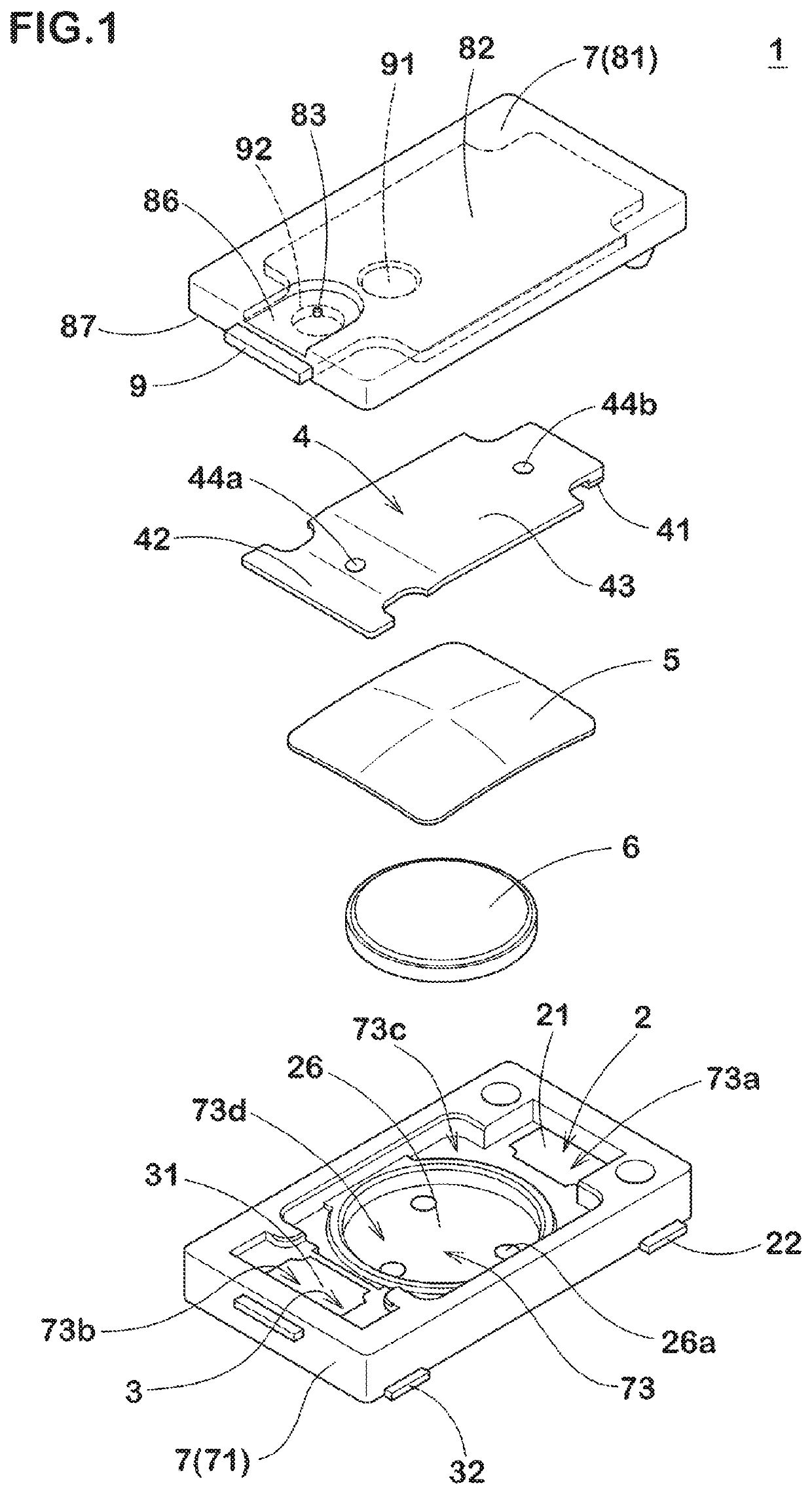
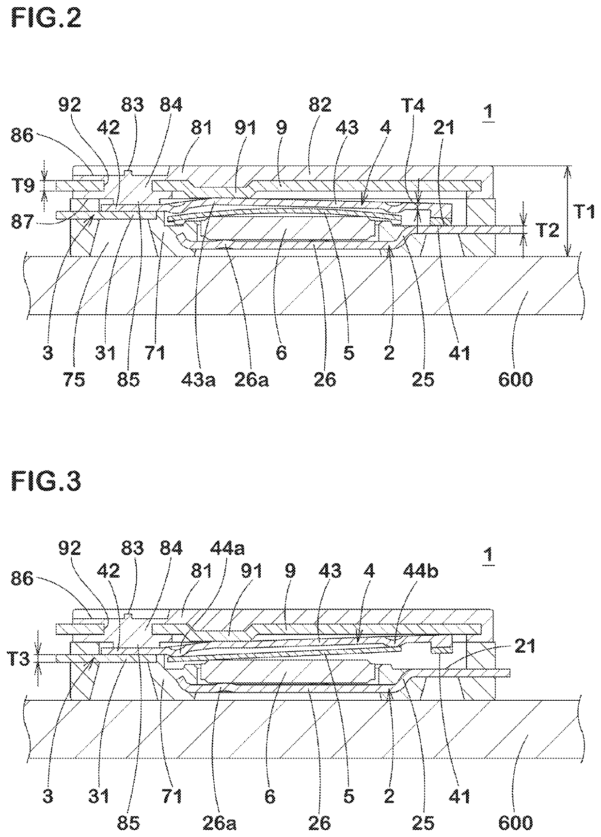
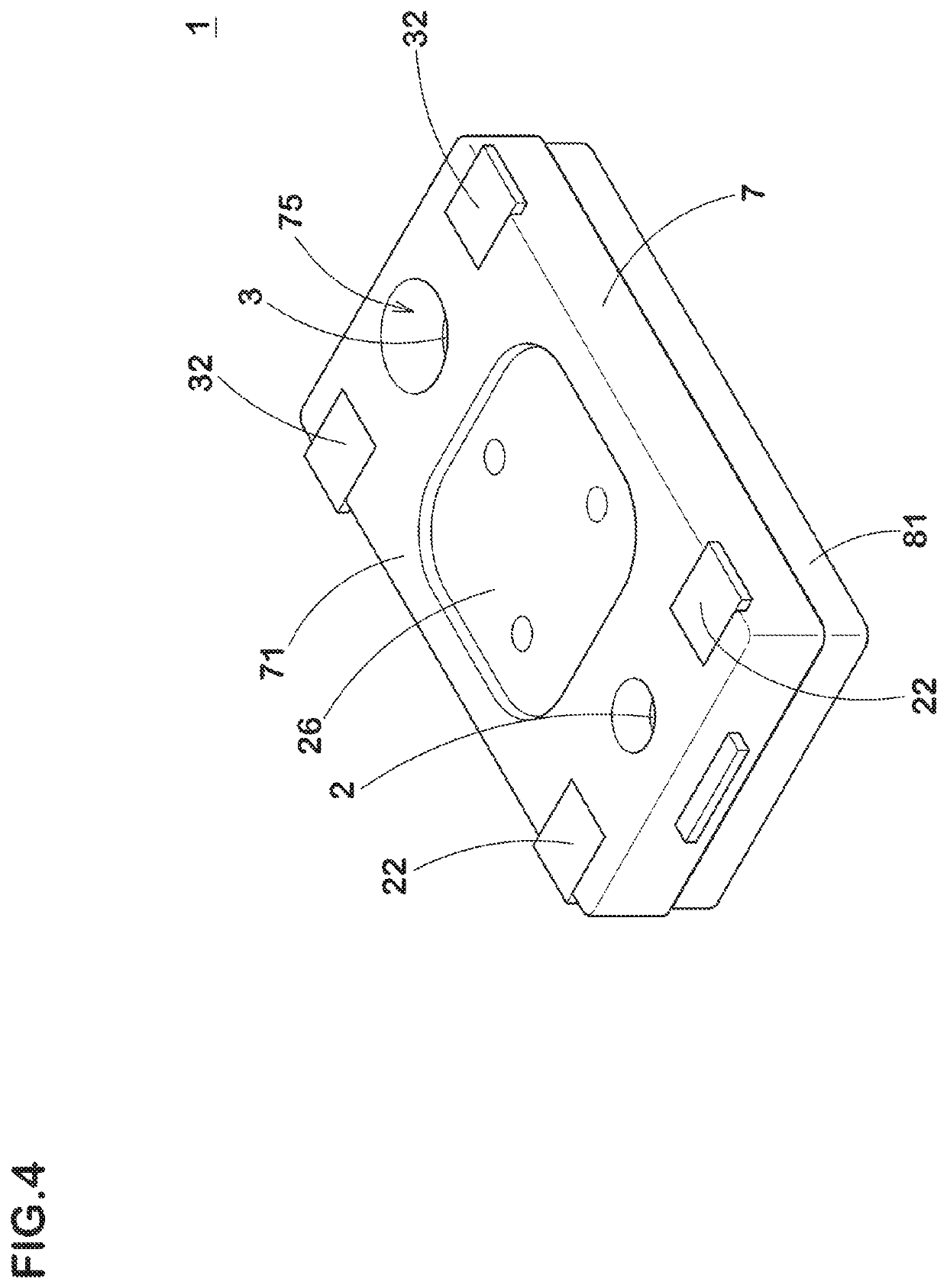
[0025]A breaker according to an embodiment of the first invention of the present invention will be described with reference to the drawings. FIGS. 1 to 4 show the configuration of the breaker. As shown in FIGS. 1 to 4, the breaker 1 is provided with a pair of terminals 22 and 32 which are partially exposed from a case 7 to the outside. The terminals 22 and 32 are electrically connected to an external circuit (not shown), therefore, the breaker 1 constitutes a main part of the safety circuit of the electric device.

[0026]As shown in FIG. 1, the breaker 1 includes a fixed piece 2 having a fixed contact 21 and the terminals 22, a terminal piece 3 having the terminals 32, a movable piece 4 having a movable contact 41 at a tip portion thereof, a thermally actuated element 5 which deforms in accordance with a temperature change, a PTC (Positive Temperature Coefficient) thermistor 6, the case 7 which accommodates the fixed piece 2, the terminal piece 3, the movable piece 4, the thermally ac...


PUM

PropertyMeasurementUnit
operating temperatureaaaaaaaaaa
temperatureaaaaaaaaaa

Abstract

A breaker 1 includes a fixed piece 2 having a fixed contact 21, a movable piece 4 including a movable contact 41 and having the movable contact 41 so as to be pressed against and in contact with the fixed contact 21, a thermally actuated element 5 shifting the movable piece 4 from a conductive state to a cut-off state in accordance with a temperature change, and a case 7 accommodating the fixed piece 2, the movable piece 4, and the thermally actuated element 5. The case 7 includes a case main body 71 accommodating the movable piece 4 and the thermally actuated element 5, a lid member 81 covering a housing concave portion 73 of the case main body 71, and a metal plate 9 embedded in the lid member 81. Heat capacity of the metal plate 9 is larger than heat capacity of the fixed piece 2.

Description

BACKGROUND OF THE INVENTIONTechnical Field[0001]The present invention relates to a small breaker and the like suitable for use in a safety circuit of an electrical device.Background Art[0002]Conventionally, a breaker is used as a protection device (safety circuit) for secondary batteries, motors, and the like of various electrical devices. When an abnormality occurs such as when the temperature of the secondary battery rises excessively during charging or discharging, or when an overcurrent flows through a motor or the like equipped in a device such as an automobile or home appliance, the breaker cuts off the current to protect the secondary batteries, the motors, and the like. In order to ensure the safety of equipment, a breaker used as such a protection device is required to operate accurately following temperature changes (to have good temperature characteristics) and to have a stable resistance value when energized.[0003]The breaker is provided with a thermally actuated element...

Claims


Application Information

Patent Timeline
Patent Type & Authority Applications(United States)
IPC IPC(8): H01H37/04H01H37/54H01H37/64H01M2/34
CPCH01M2/348H01H37/04H01H37/54H01H37/64H01H2037/046H01H2037/5463H01H37/5418H01H37/5436H01H37/043H01H37/12Y02E60/10H01M2200/10H01M2200/101H01M2200/106H01M50/581
Inventor NAMIKAWA, MASASHI
Owner BOURNS KK
Why Eureka
Try Eureka