
Magnet holder, sensor magnet assembly, electric motor comprising a sensor magnet assembly, and method for producing a sensor magnet assembly

a technology of magnet holder and sensor magnet, which is applied in the direction of magnetic measurement, dynamo-electric components, instruments, etc., can solve the problems of inability to tolerate major protrusions, radial directions, and difficulty in mechanical deformation of sintered materials, and achieve the effect of sufficient strength and durability

Active Publication Date: 2020-04-30
BUHLER MOTOR GMBH
View PDF0 Cites 0 Cited by
  • Summary
  • Abstract
  • Description
  • Claims
  • Application Information

AI Technical Summary

Benefits of technology

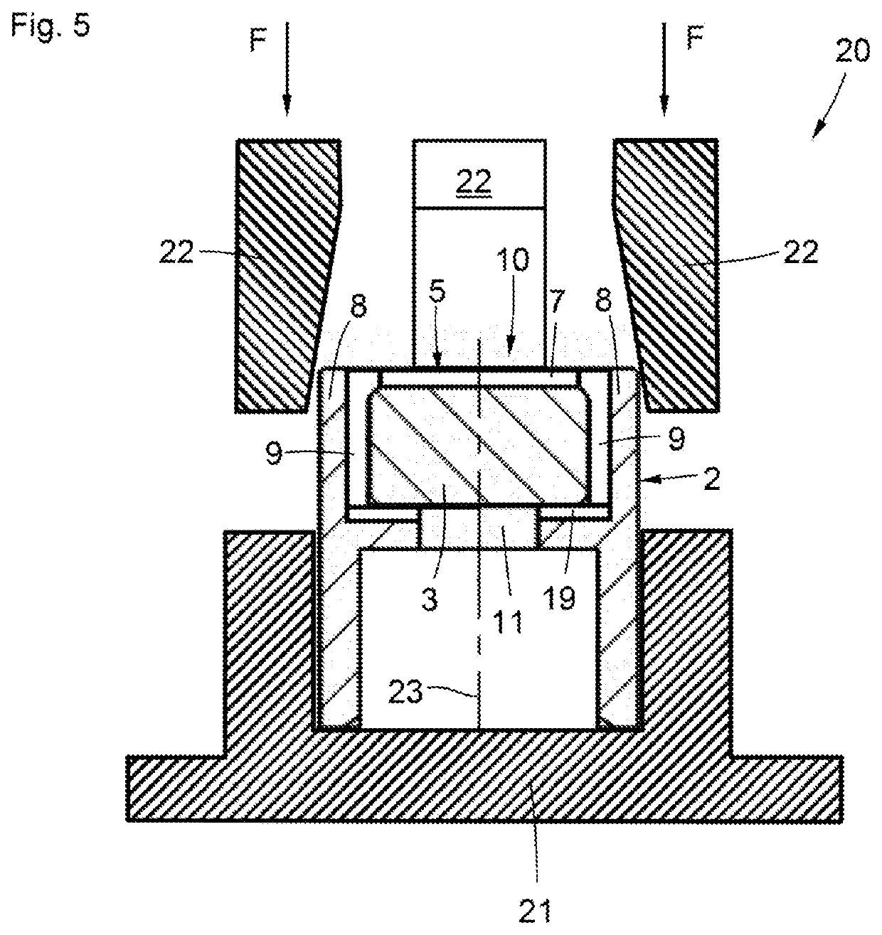
The present invention provides a simple and reliable method to attach a sensor magnet to a motor shaft using an adhesive-free solution. The connection is provided by a form fit in multiple locations with a greater wall thickness, ensuring durability. The optimal arrangement of pressing jaws is applied at an angle of 10 to 45 degrees, specifically at an angle of 20 degrees, to facilitate deformation of the wall. This enables a very effective attachment of the sensor magnet to the motor shaft.

Problems solved by technology

In the present invention, it is not possible to tolerate any major protrusions in both the axial and radial directions, because this would entail an increase in the air gap as well as space problems.
Mechanical deformation of sintered material is difficult under these conditions and results in material failures when using conventional means and methods.
This design makes it easier to deform sintered parts; however, this comes at the expense of robustness and durability.

Method used


Image

  • Magnet holder, sensor magnet assembly, electric motor comprising a sensor magnet assembly, and method for producing a sensor magnet assembly
  • Magnet holder, sensor magnet assembly, electric motor comprising a sensor magnet assembly, and method for producing a sensor magnet assembly
  • Magnet holder, sensor magnet assembly, electric motor comprising a sensor magnet assembly, and method for producing a sensor magnet assembly

Examples


Embodiment Construction

[0024]In describing preferred embodiments of the present invention illustrated in the drawings, specific terminology is employed for the sake of clarity. However, the invention is not intended to be limited to the specific terminology so selected, and it is to be understood that each specific element includes all technical equivalents that operate in a similar manner to accomplish a similar purpose.

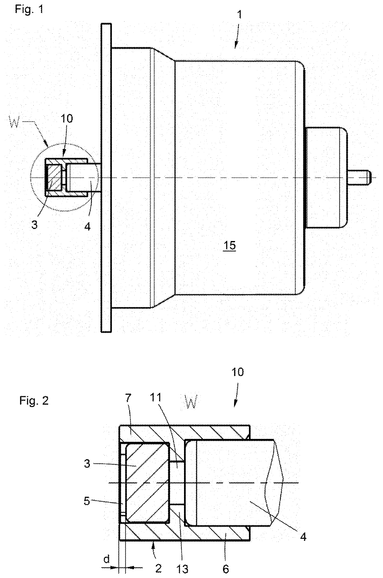
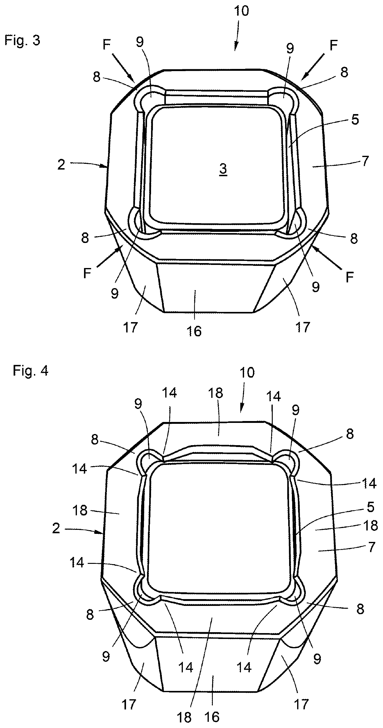
[0025]FIG. 1 shows an open electric motor 1 comprising a motor housing 15, a motor shaft 4 projecting out of the housing, and a sensor magnet assembly 10 composed of a magnet holder 2 and a sensor magnet 3 attached to the motor shaft 4.

[0026]FIG. 2 shows an enlarged illustration of the sensor magnet assembly 10 (Detail W), including the magnet holder 2, the sensor magnet 3, and the motor shaft 4. The sensor magnet 3 is accommodated in a receiving recess 5 of the magnet holder 2 and is pressed with a bushing-shaped attachment region 6 onto the motor shaft 4. In order to define the press-in...


PUM


Abstract

A magnet holder for attaching a sensor magnet to a motor shaft of an electric motor, including a receiving recess for the sensor magnet and an attachment region for attachment to the motor shaft, wherein the receiving recess is radially delimited by a wall that, over the circumference thereof, includes a plurality of weak spots which have a reduced wall thickness and are designed so that free spaces remain between the weak spots and the sensor magnet arranged in the receiving recess. The invention further relates to a sensor magnet assembly, to an electric motor comprising a sensor magnet assembly, and to a method for producing a sensor magnet assembly. It is the object of the present invention to very reliably and durably attach a sensor magnet to the end of a motor shaft in a very economical and simple manner, wherein adhesive methods are to be dispensed with.

Description

CROSS-REFERENCE TO RELATED APPLICATIONS[0001]The present patent application is based on, and claims priority from, German Application No. DE 10 2018 218 430.5, filed Oct. 29, 2018, which is incorporated herein by reference in its entirety.BACKGROUND OF THE INVENTION(1) Field of the Invention[0002]The invention relates to a magnet holder for attaching a sensor magnet to a motor shaft of an electric motor. The invention further relates to a sensor magnet assembly, to an electric motor comprising a sensor magnet assembly, and to a method for producing a sensor magnet assembly.(2) Description of Related Art Including Information Disclosed Under 37 CFR 1.97 and 1.98[0003]A magnet holder of the type in question, a sensor magnet assembly and an electric motor comprising the sensor magnet assembly are known from WO 2017131296 A1. In this case, the sensor magnet is rectangular, in particular square, and is inserted into a recess of a magnet holder. The sensor magnet is glued in for attachmen...

Claims


Application Information

Patent Timeline
Patent Type & Authority Applications(United States)
IPC IPC(8): H02K29/08H02K11/215
CPCH02K11/215H02K29/08G01R33/07G01D11/00
Inventor GEHRING, NILSGOLDITZ, PAUL-PETERSCHNEIDER, PETERBAUDLER, BERTRAMMEHL, GERHARDKACH, STEPHAN
Owner BUHLER MOTOR GMBH
Learn More