Touchpad module
a technology of touchpad and module, applied in the field of touchpad module, can solve the problems of poor initial operation responsiveness, disadvantageous downsizing and thinning of actuators,
- Summary
- Abstract
- Description
- Claims
- Application Information
AI Technical Summary
Benefits of technology
Problems solved by technology
Method used
Image
Examples
first embodiment
Main Operation and Effect of First Embodiment
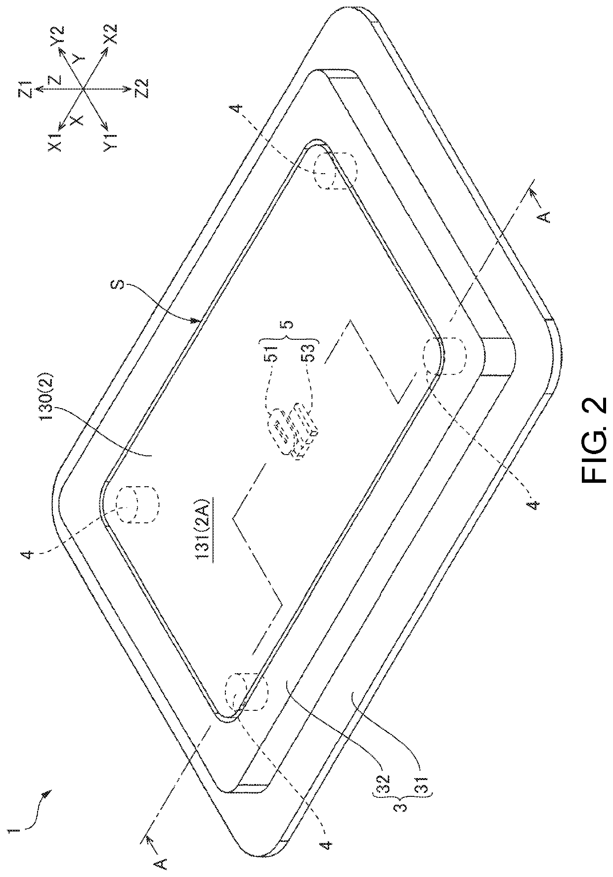
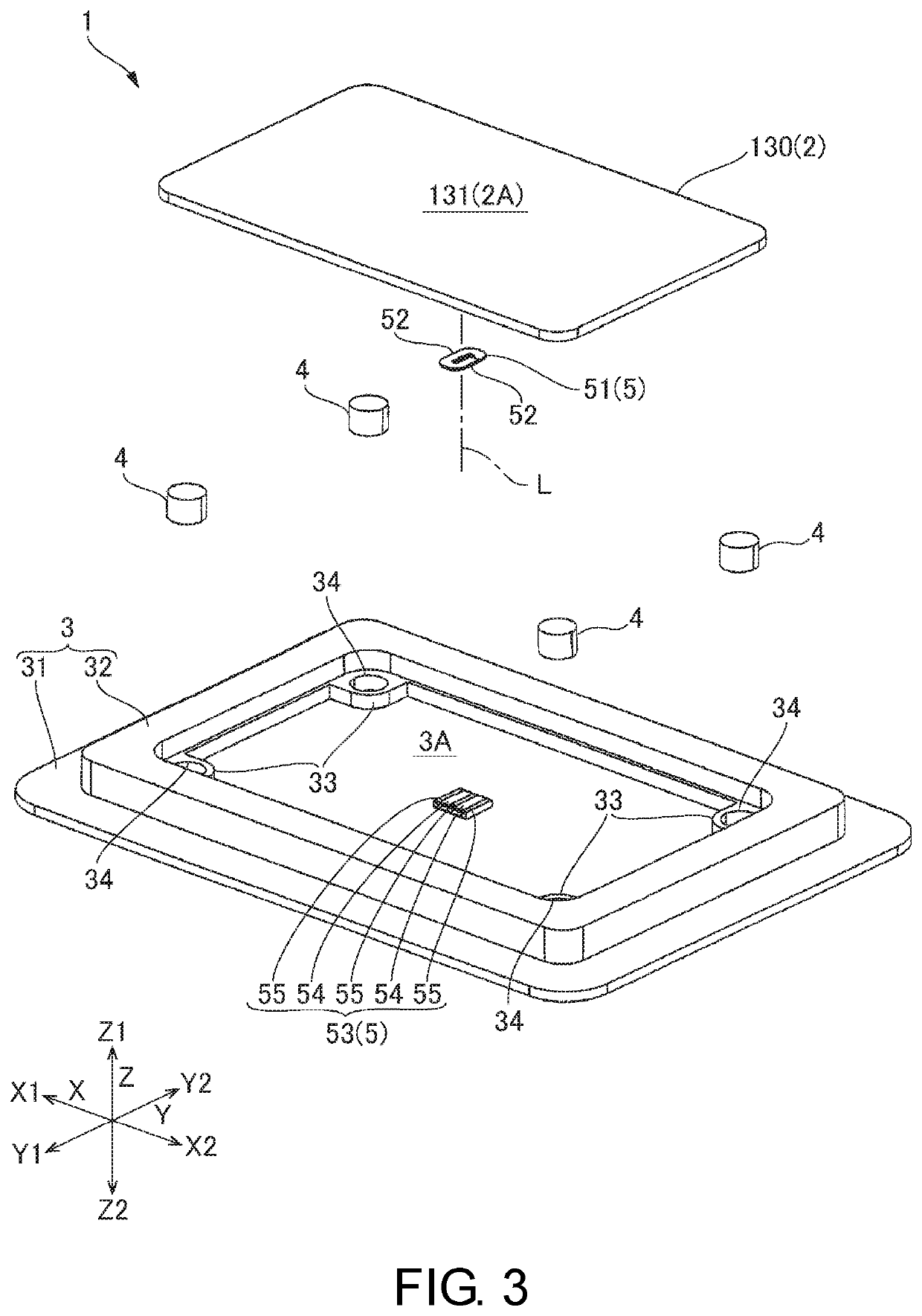
[0044]As described above, the touchpad module 1 according to the first embodiment includes the movable plate 2 in which the operation surface 131 of the touchpad 130 is arranged on one surface 2A, the support member 3 including the facing portion 3A facing the other surface 2B of the movable plate 2, the damper members 4 for connecting the movable plate 2 and the support member 3, and the actuator 5 for vibrating the movable plate 2. The actuator 5 includes the air-core coil 51 and the magnet 53 facing each other in the first direction Z in which the other surface 2B faces the facing portion 3A. One of the air-core coil 51 and the magnet 53 is fixed to the other surface 2B, and the other is fixed to the facing portion 3A.
[0045]In the first embodiment, the number of components of the actuator 5 arranged between the movable plate 2 and the support member 3 is small, the air-core coil 51 is directly fixed to the other surface 2B of the movab...
second embodiment
Main Operation and Effect of Second Embodiment
[0060]As described above, similar to the first embodiment, the touchpad module 1A according to the second embodiment includes the actuator 5A that vibrates the movable plate 2. The actuator 5A includes the air-core coil 51 and the magnet 53, which face each other in the first direction Z in which the other surface 2B of the movable plate 2 faces the facing portion 3A, one of the air-core coil 51 and the magnet 53 is fixed to the other surface 2B of the movable plate 2, and the other is fixed to the facing portion 3A of the support member 3.
[0061]In the actuator 5A according to the second embodiment, the air-core coil 51 is fixed to the other surface 2B through the substrate 61 connected to the air-core coil 51, and the magnet 53 is fixed to the facing portion 3A through the yoke 73 in contact with the magnet 53. In this way, the coil unit 60 and the magnet unit 70 are in a state of being separated from each other without being contained ...
modification example
[0065](1) In each embodiment described above, the air-core coil 51 and the magnet 53 can be reversely disposed. That is, the air-core coil 51 is fixed to the facing portion 3A of the support member 3, and the magnet 53 is fixed to the other surface 2B of the movable plate 2. In this case, since the magnet unit 70 according to the second embodiment is mounted on the movable plate 2, the frame 71 can be made function as a pendulum. Accordingly, by adjusting the weight of the frame 71, it is possible to make the resonance frequency of a vibration system in which the movable plate 2 and components fixed to the movable plate 2 are supported by the damper members 4 so as to be able to vibrate coincide with the vibration frequency of the movable plate 2.
[0066](2) In each embodiment described above, the vibration direction of the movable plate 2 is the second direction X; however, it is possible to set the vibration direction of the movable plate 2 to the third direction Y by rotating the a...
PUM
 Abstract
Description
Claims
Application Information
 - R&D
- Intellectual Property
- Life Sciences
- Materials
- Tech Scout
- Unparalleled Data Quality
- Higher Quality Content
- 60% Fewer Hallucinations
Browse by: Latest US Patents, China's latest patents, Technical Efficacy Thesaurus, Application Domain, Technology Topic, Popular Technical Reports.
© 2025 PatSnap. All rights reserved.Legal|Privacy policy|Modern Slavery Act Transparency Statement|Sitemap|About US| Contact US: help@patsnap.com


