
A carbon capture membrane

Active Publication Date: 2020-04-30
SINGAPORE UNIVERSITY OF TECHNOLOGY AND DESIGN
View PDF0 Cites 2 Cited by
  • Summary
  • Abstract
  • Description
  • Claims
  • Application Information

AI Technical Summary

Benefits of technology

The invention is a thin and light carbon capture membrane that can be easily adapted to fit with existing infrastructure or process lines. It can be integrated into a modular system to switch between fresh and used membranes for fouling. The used membranes can be easily taken offline for regeneration. The technical effect is to provide a flexible and efficient solution for carbon capture.

Problems solved by technology

The liquid and solid absorbers are packed in large scale tanks / containers, and hence a drawback of the current technologies is the bulky and heavy forms.
The identification of suitable storage locations for the captured CO2 also presents an immense challenge for the CO2 capture industry.
In addition, the high energy penalties and carbon footprint (e.g., energy costs for refrigeration) of current CO2 capture technologies serve as further barriers to the wide implementation CO2 capture.
The subsequent linear scale-up costs further accelerate the design time of larger scale units.
However, the large pressure drop or pressure build-up of the membrane limits its application as a separation / capture material.

Method used


Image

  • A carbon capture membrane
  • A carbon capture membrane
  • A carbon capture membrane

Examples


example

Example 1

Preparation of PEI@silica

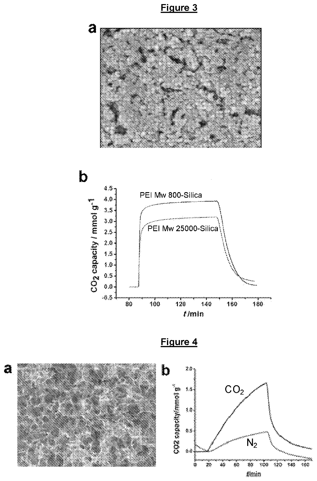
[0102]5 g of polyethylenimine (PEI) having a molecular weight of 800 Da was dissolved in 50 mL of methanol. This solution was then added stepwise under stirring to 5 g of fumed silica suspension in 50 mL methanol. The mixture was stirred for more than 2 hours to ensure a good dispersion of the polyethylenimine on the silica support.

example 2

Preparation of PEI@silica Modified Commercial Filtration Membranes

[0103]PEI(800)@silica was modified on a commercial filtration membrane (PVDF) and a polyethersulfone (PES) ultrafiltration flat sheet membrane through a filtration method (Wan S et al, 2016, Adv. Mater., 28:7862-7898). A layer of PEI@silica was successfully modified on the PVDF and PES membranes and simultaneously, pores of the filtration membranes were covered. However, since the porous networks of the PVDF and PES membranes are random and tortuous, an undesirable high pressure drop across the membrane was experienced.

example 3

Preparation of PEI©GO Complexes

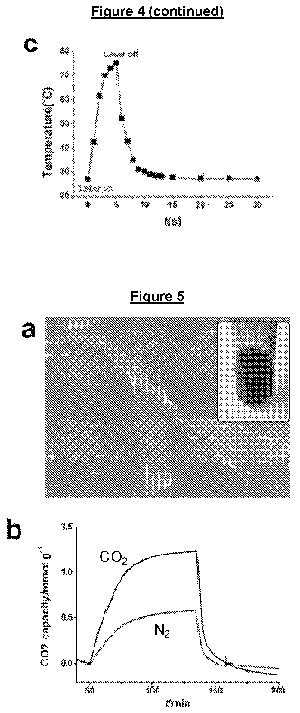
[0104]The PEI©GO as shown in FIG. 4 is prepared by the following method. GO was prepared by a modified Hummers method (J. Mater. Chem. A, 2015, 3:1142-1151) Aqueous GO dispersion was sonicated in ice-water bath for 6 hours prior to use. The pH value of GO (10 mg / mL) was adjusted to 8.0 gradually with 1 M NaOH aqueous solution. Then GO dispersion (10 mg / mL) was mixed with PEI (6.25 mg / mL) aqueous solution under intense stirring to produce a PEI-GO complex with the concentration of PEI and GO being 5 mg / ml and 2 mg / mL, respectively. The resultant complex solution was thermally annealed in a 90° C. oil bath for 3 hours with vigorous stirring to produce PEI-GO complex solution.


PUM

PropertyMeasurementUnit
Thicknessaaaaaaaaaa
Thicknessaaaaaaaaaa
Diameteraaaaaaaaaa

Abstract

There is provided a carbon capture mixed matrix membrane comprising: a polymeric support layer; and a carbon dioxide capture layer in contact with the polymeric support layer, the carbon dioxide capture layer comprising solid porous material with at least one carbon dioxide adsorption site, wherein the polymeric support layer comprises spatially ordered uniform sized pores. The polymeric support layer may be patterned by micro-molding, nanoimprinting, mold-based lithography or other suitable lithographic process. The carbon dioxide capture layer may comprise amine-functionalised material, metal-organic frameworks such as zeolite imidazolate framework 8 (ZIF-8) or copper benzene-1,3,5-tricarboxylate (Cu-BTC) which may or may not be amine modified. There is also provided a membrane module comprising at least one carbon capture mixed matrix membrane and a method of forming the carbon capture mixed matrix membrane.

Description

TECHNICAL FIELD[0001]The present invention relates to a carbon capture membrane, a membrane module comprising the carbon capture membrane and a method of forming the carbon capture membrane.BACKGROUND[0002]Commercial carbon dioxide (CO2) separation technologies are based primarily on chemical solvent absorption method through the use of bulk liquids or solids such as liquid amine-based solution and soda lime granule. These technologies are currently used in industrial, submarine and spaceship environment. The liquid and solid absorbers are packed in large scale tanks / containers, and hence a drawback of the current technologies is the bulky and heavy forms. In particular, the current principal capture technology relies heavily on the use of a liquid solvent to separate CO2 from N2. This method typically requires additional processing steps where CO2 is desorbed, concentrated to required levels before finally being compressed and liquefied to be transported or stored. The identificati...

Claims


Application Information

Patent Timeline
IPC IPC(8): B01D69/10B01D53/22B01D71/56B01D71/80B01D71/34B01D71/68B01D67/00B01D69/14
CPCB01D69/141B01D71/56B01D69/10B01D71/34B01D53/228B01D71/68B01D2323/46B01D71/80B01D67/0088B01D2325/02B01D2325/04B01D2257/504B01D67/0032B01D67/0079B01D69/12B01D69/148B01D71/024B01D71/028B01D2323/345B01D71/021B01D71/52B01D67/0006Y02C20/40B01D2323/52B01D69/106B01D69/1071B01D71/0211B01D71/0281B01D71/421B01D71/441B01D71/601B01D69/107B01D67/00793B01D2325/0283
Inventor TAN, MEI CHEELOW, HONG YEEZHANG, YUANYUANWONG, HIM CHENG
Owner SINGAPORE UNIVERSITY OF TECHNOLOGY AND DESIGN
Learn More