
Non-linear optical mapping of sal seeker detector array

a detector array and non-linear optical mapping technology, applied in the field of detector arrays, to achieve the effect of increasing overall fov and extending spatial rang

Active Publication Date: 2020-04-23
BAE SYST INFORMATION & ELECTRONICS SYST INTERGRATION INC
View PDF0 Cites 0 Cited by
  • Summary
  • Abstract
  • Description
  • Claims
  • Application Information

AI Technical Summary

Benefits of technology

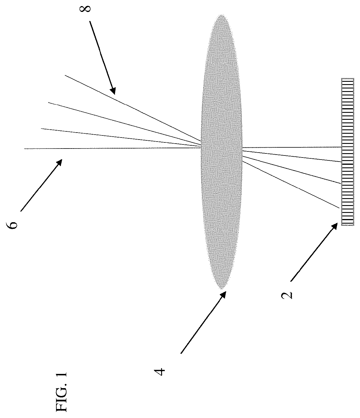
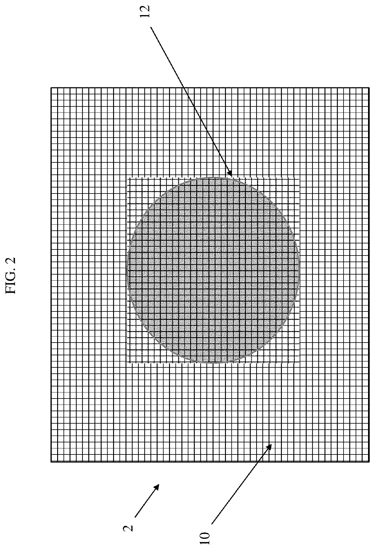
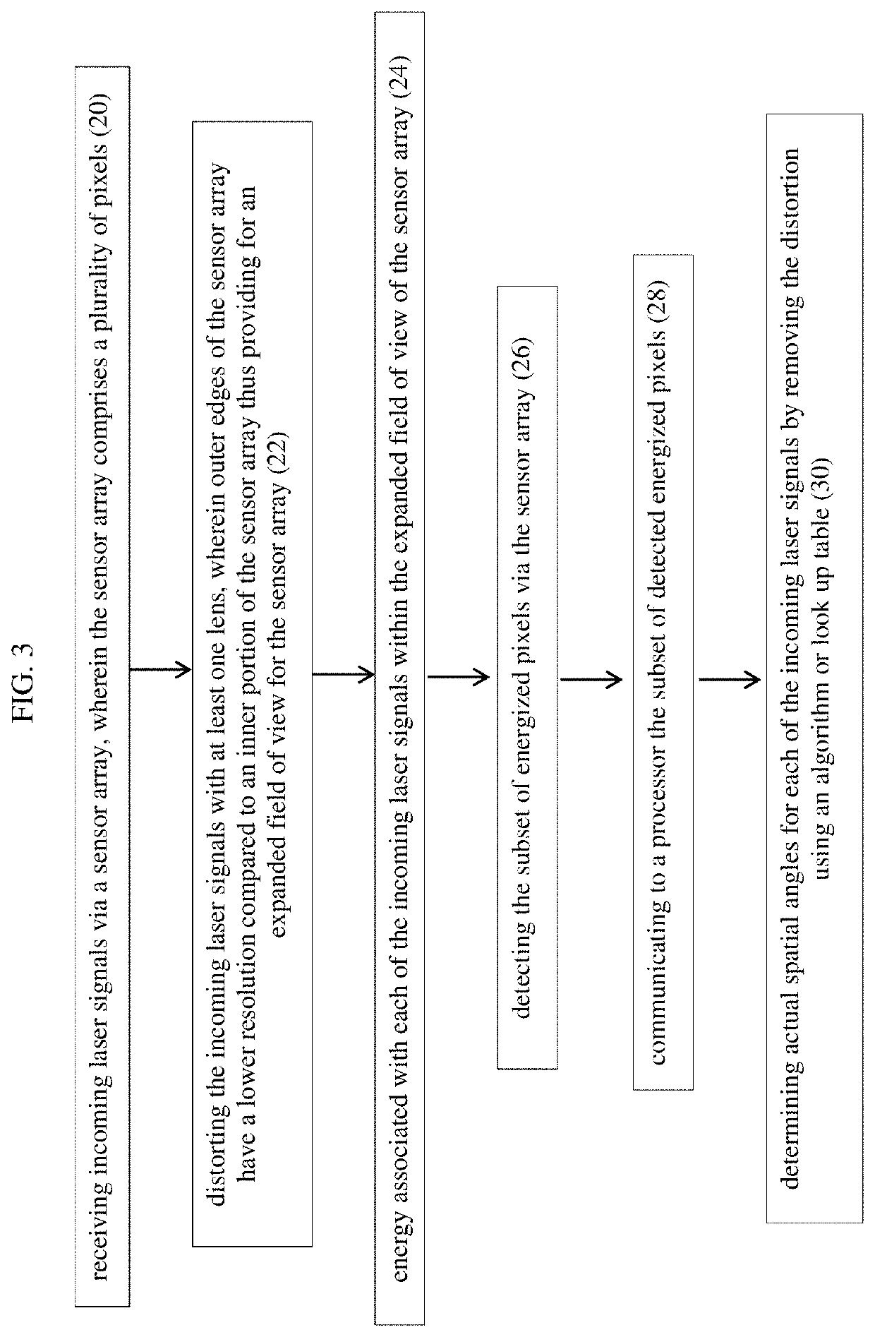
The patent describes a system and method for improving the resolution and coverage of a detector array by applying non-linear distortion to the optics. This allows for better spatial resolution in the center of the field of view (FOV) while relaxing the outer regions. The non-linear distortion is applied using a lens that provides increased FOV at the expense of spatial resolution. The system can be used in various applications such as terminal guidance and ground-based tracking. The non-linear distortion can be linear or radial in direction, depending on the requirements of the application. The method involves detecting the incoming signals, applying the non-linear distortion, and removing it using an algorithm or look up table to produce a pixel by pixel correction. The system and method provide improved performance and efficiency in various optical mapping applications.

Problems solved by technology

This forces the design trade-off between maximizing the FOV at the expense of spatial resolution.

Method used


Image

  • Non-linear optical mapping of sal seeker detector array
  • Non-linear optical mapping of sal seeker detector array
  • Non-linear optical mapping of sal seeker detector array

Examples


Embodiment Construction

[0020]One embodiment of the system of the present disclosure could be used for any semi-active laser (SAL) seeker weapon or imager where higher resolution / eye acuity is needed when looking forward and less resolution is needed around the edges of the field of view (FOV) for peripheral vision queuing. In one embodiment, the system allows customization of the FOV accuracy through optical design. By modifying the distortion performance of the lens design, the angular performance of the system can be traded for extended FOV coverage. The trade can be non-linear, thus preserving high angle accuracy in the center of the FOV while rolling off toward the edge of the FOV.

[0021]In one embodiment, a SAL seeker's performance is optimized between the FOV and the angle accuracy as function of the FOV. Using lens distortion, one can vary the detector array's instantaneous field of view (ifov) over the FOV such that there is a higher angular accuracy in the center zone of the FOV and a queuing area...


PUM


Abstract

The system and method non-linear optical mapping of a detector array to expand the field of view. Outer edges of the sensor array having lower resolution spatial resolution in exchange for an expanded field of view. A lens is used to distort incoming signals to provide the expanded field of view and a processor is used to remove the distortion to provide the actual spatial angles for the incoming signals suing a look up table or an algorithm. The lens may create radial or linear distortion.

Description

FIELD OF THE DISCLOSURE[0001]The present disclosure relates to detector arrays and more particularly to using a non-linear mapping technique to extend the field of view coverage of a semi-active laser (SAL) seeker or other optical device.BACKGROUND OF THE DISCLOSURE[0002]The typical SAL seeker approach uses a linear mapping of angle space to linear space on the detector array. In that situation, each pixel represents an instantaneous Field of View (iFOV) that is simply the FOV divided by the number of pixels within the array. This forces the design trade-off between maximizing the FOV at the expense of spatial resolution.[0003]Wherefore it is an object of the present disclosure to overcome the above-mentioned shortcomings and drawbacks associated with the conventional detector arrays.SUMMARY OF THE DISCLOSURE[0004]In the case of a SAL seeker, resolution is typically needed in the center of the FOV, but not at the outer regions of the FOV. By applying a nonlinear distortion to the op...

Claims


Application Information

Patent Timeline
IPC IPC(8): H01S3/00G02B27/00G02B27/09
CPCG02B27/0037G02B27/0955H01S3/0085G02B3/02G02B27/0025F41G7/226F41G7/2293
Inventor CHOINIERE, MICHAEL J.
Owner BAE SYST INFORMATION & ELECTRONICS SYST INTERGRATION INC
Learn More