Refiner apparatus and a method for refining cellulosic material

a cellulosic material and refiner technology, applied in the field of refiner plate segments, can solve the problems of high energy consumption of prior art refining systems, inefficiency, and frequent change of refiner plate segments, so as to reduce the effect of grinding material and reduce the energy needed for the process. , the effect of high quality

Active Publication Date: 2020-04-23
DAPROKS AB
View PDF0 Cites 2 Cited by
  • Summary
  • Abstract
  • Description
  • Claims
  • Application Information

AI Technical Summary

Benefits of technology

[0010]In such way is achieved a refiner for use in a cost-effective manner by reducing the consumption of energy by means of a steam explosion process and still achieving an improved and uniform quality of biomass pulp for the production of e.g. paper. By means of such “explosion pulping” of the—with liquid, e.g. pure water—saturated cellulosic material (and grinded by the discs), a sudden volatilization of the liquid, entrapped within interstices (pores) of the cellulosic material, is achieved. Thus literally, an “exploding” of the material is noticed when ejected from the refining gap and beyond the outer edge to the outer environment, i.e. from high pressure environment to lower pressure environment. By means of the high pressure environment in the refining gap, which high pressure being increased by means of the barrier arrangement and maintained out to the outer edge of the disc arrangement (comprising at least two grinding discs), the pressure liquid of the saturated cellulosic material can be retained in liquid phase all the way out to the outer edge within the refining gap. Due to the achieved high pressure in the refining gap, the boiling point of the liquid (pure water or mixed water with chemicals or other) of the material can be raised compared with traditional refiners. This implies a boiling point (steam point) at relatively high temperature, thus achieving an extremely cost-effective refining process of the pulp in the refining gap. The refiner plate is combined with other refiner plates and being mounted on the discs to reach optimal grinding. The grinding bars of the respective plate segment are oriented in such way that a pumping of the saturated cellulosic material is achieved propelling the material in radial direction and / or in direction towards the outer edge. At the same time, the centrifugal force, achieved by the rotation of the at least one disc, also forces the hot saturated cellulosic material (the water being in liquid phase) towards the outer edge. By means of the barrier arrangement provided at a limited area of the disc outer edge, and the pump action of the discs, the centrifugal force, and the high boiling point of the liquid of the material due to the created high pressure, the vaporation is controlled to be performed at the outer edge perimeter of the disc arrangement. The vaporation is thus performed in a step of bringing the grinded fiber material from high pressure to low pressure outside the refining gap and barrier arrangement thereby achieving the above-mentioned “explosion pulping”. Upon the sudden discharge of the material / water (liquid) / steam mixture from the refining gap, the water (liquid) trapped within the interstices of the cellulosic material will go to steam, thereby providing the necessary energy to produce a high quality “fluffy” pulp mass suitable for e.g. paper making. Vaporation is herein defined as change of a liquid or solid substance to a gas or vapor.
[0046]In such way the high pressure in the refining gap can be maintained and the motion of the material and liquid is guaranteed towards the outer edge and the pressure peak point is forced out to the outer edge and the barrier arrangement.

Problems solved by technology

Prior art refining systems have high energy consumption and the flow-through of cellulosic material to be grinded is rather slow and not efficient.
The quality of the achieved pulp is often not the same for one production cycle as for another and the refiner plate segments have to be changed quite frequently due to high wear of the grinding bars of the segments.

Method used


Image

  • Refiner apparatus and a method for refining cellulosic material
  • Refiner apparatus and a method for refining cellulosic material
  • Refiner apparatus and a method for refining cellulosic material

Examples


Embodiment Construction

[0063]Hereinafter, embodiments of the present invention will be described in detail with reference to the accompanying drawings, wherein for the sake of clarity and understanding of the invention some details of no importance are deleted from the drawings.

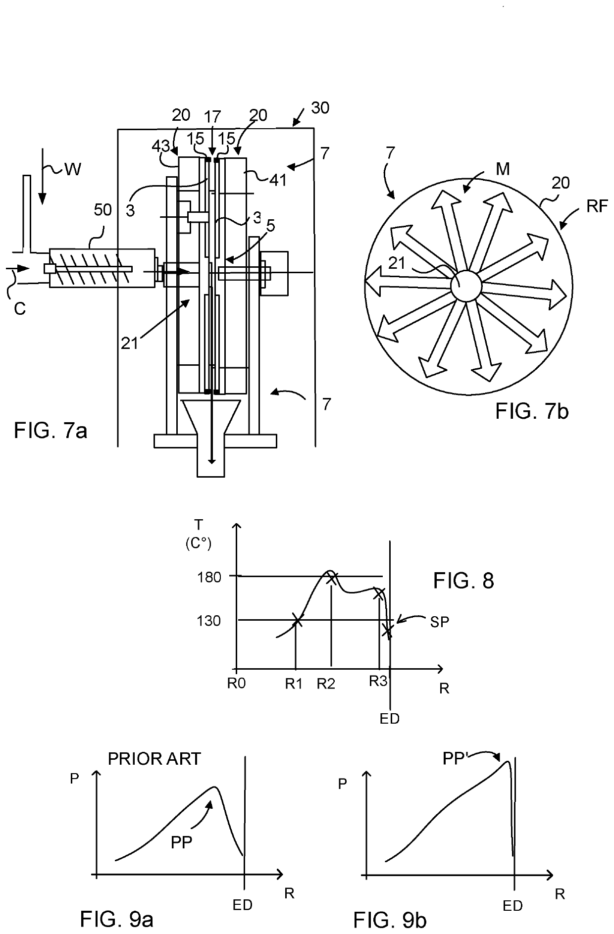
[0064]FIG. 1 illustrates a refiner plate segment 1 showing its interior side comprising a pattern of grinding bars 3. The refiner plate segment 1 together with other refiner plate segments 1 is to be arranged on a first (rotor) and second (stator) refiner discs. The refiner plate segments 1 mounted on the refiner discs constitute an important component of a disc-type refiner apparatus (not shown, see for example FIG. 10), which is adapted to grind a saturated cellulosic material in a refining gap (not shown) defined by the opposed discs during use of the apparatus, the saturated cellulosic material being moved from a refiner inlet opening of e.g. the stator towards an outer edge of the refiner plate segment. The grinding bars 3 are...


PUM

PropertyMeasurementUnit
pressureaaaaaaaaaa
temperatureaaaaaaaaaa
perimeteraaaaaaaaaa

Abstract

The present invention regards a refiner plate segment (1) for a disc-type refiner apparatus (30), adapted to grind a saturated cellulosic material (M) in a refining gap (17) defined by opposed discs (20) during use of the apparatus (30), the material being moved from a refiner inlet opening (21) towards an outer edge (7) of the segment (1). The outer edge (7) of the segment (1) comprises a barrier arrangement (15) to increase the pressure in the refining gap (17) for retaining the liquid phase out to said outer edge (7). The present invention also regards a method of refining a saturated cellulosic material (M) in a refining gap (17) defined by two opposed discs (20) of a disc arrangement.

Description

CROSS REFERENCE TO RELATED APPLICATIONS[0001]This application is a divisional of U.S. application Ser. No. 15 / 115,624, filed Jul. 29, 2016, which is a U.S. National Phase Application of PCT International Application Number PCT / SE2015 / 050134, filed on Feb. 6, 2015, designating the United States of America and published in the English language, which is an International Application of and claims the benefit of priority to Swedish Patent Application No. 1450143-1, filed on Feb. 11, 2014. The disclosures of the above-referenced applications are hereby expressly incorporated by reference in their entireties.BACKGROUNDField[0002]The present invention regards a refiner plate segment as being defined by the preamble of claim 1. The invention also regards a refiner apparatus as defined in claim 5 and a method of refining a saturated cellulosic material according to claim 11. The present invention regards a disc-type refiner apparatus of a refiner plate steam management system.[0003]The prese...

Claims


Application Information

Patent Timeline
Patent Type & Authority Applications(United States)
IPC IPC(8): D21B1/36B02C23/02B02C7/11B02C7/14D21D1/30B02C7/12
CPCB02C7/14B02C7/12D21D1/30B02C7/11B02C23/02D21B1/36D21B1/14D21D1/303D21D1/306D21C1/02
Inventor ÅKERBLOM, BENGT
Owner DAPROKS AB
Why Eureka
Try Eureka