Sensor device and gas monitoring system
- Summary
- Abstract
- Description
- Claims
- Application Information
AI Technical Summary
Benefits of technology
Problems solved by technology
Method used
Image

Examples
embodiment 1
1. Configuration of Gas Monitoring System
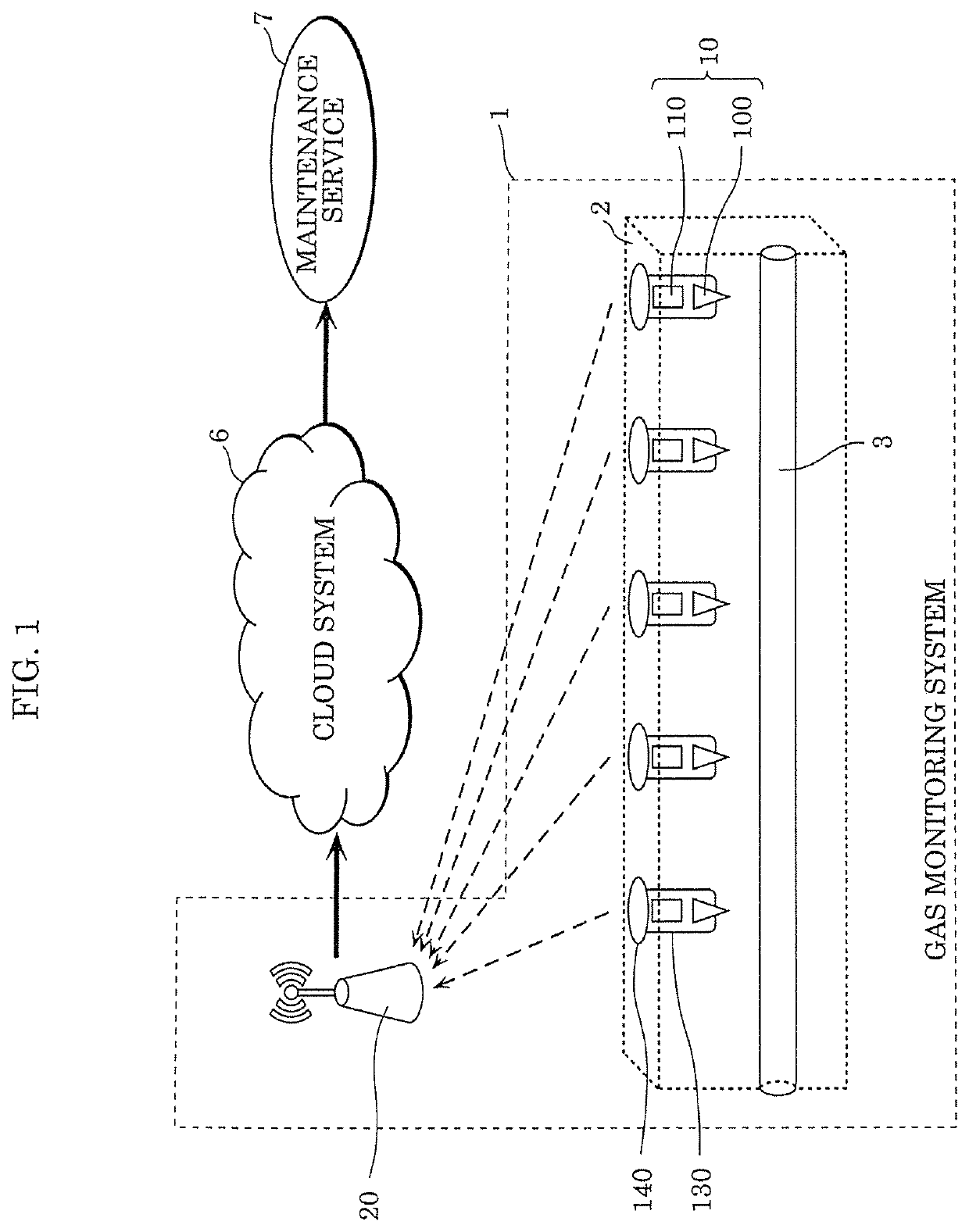
[0028]FIG. 1 is an overall diagram of gas monitoring system 1 according to Embodiment 1. Gas monitoring system 1 is a system that detects gas leaks of gas supplied by pipeline 3 buried in ground 2 at all times. Hereinafter, gas monitoring system 1 that detects hydrogen leaks will be described with the gas supplied by pipeline 3 being described as gas containing hydrogen. Gas containing hydrogen is a collective term for gas including molecules with hydrogen atoms, and can include, for example, hydrogen, methane and alcohol.
[0029]As illustrated in FIG. 1, gas monitoring system 1 includes at least one sensor device 10 buried in ground 2, and gateway 20. Sensor device 10 is disposed, for example, above pipeline 3 that is a transportation route for gas containing hydrogen. Sensor device 10 detects gas containing hydrogen leaked from pipeline 3. A configuration of sensor device 10 will be described in more detail later.
[0030]Sensor device 10 transm...
embodiment 2
[0085]Gas monitoring system 1 according to Embodiment 2 will be described next.
[0086]Gas monitoring system 1 according to the present embodiment differs from gas monitoring system 1 described in Embodiment 1 in that sensor module 100a includes communication circuit 109 for wirelessly communicating with communication module 110.
[0087]FIG. 10 is a cross-sectional view of a configuration of sensor module 100a according to the present embodiment. As illustrated in FIG. 10, sensor module 100a according to the present embodiment includes sensor circuit 102a, power sources 107 and 108, and communication circuit 109.
[0088]Sensor circuit 102a has the same configuration as detector 105 of sensor circuit 102 described in Embodiment 1. Sensor circuit 102a does not include power source 106 and operates by being supplied with electric power from power source 107 disposed outside of sensor circuit 102a. In other words, in the present embodiment, power source 107 is the first power source. Sensor c...
embodiment 3
[0093]Gas monitoring system 1 according to Embodiment 3 will be described next.
[0094]Gas monitoring system 1 according to the present embodiment differs from gas monitoring system 1 described in Embodiment 1 in that sensor device 10 is disposed in road rivet 240.
[0095]FIG. 12 is an overall diagram of gas monitoring system 1 according to the present embodiment. FIG. 13 is a diagram showing an arrangement of sensor module 100 and communication module 110 according to the present embodiment.
[0096]In gas monitoring system 1 according to the present embodiment, sensor device 10 is disposed in road rivet 240. Road rivet 240 is a rivet indicating traffic lines, etc., and a portion thereof is buried in ground 2. For example, road rivet 240 is disposed on a centerline of a roadway, a boundary line between a roadway and a service road, etc. at a predetermined interval. Road rivet 240 includes a metal, polycarbonate resin, etc., and, as illustrated in FIG. 12, sensor module 100 and communicati...
PUM
 Abstract
Description
Claims
Application Information
 - R&D
- Intellectual Property
- Life Sciences
- Materials
- Tech Scout
- Unparalleled Data Quality
- Higher Quality Content
- 60% Fewer Hallucinations
Browse by: Latest US Patents, China's latest patents, Technical Efficacy Thesaurus, Application Domain, Technology Topic, Popular Technical Reports.
© 2025 PatSnap. All rights reserved.Legal|Privacy policy|Modern Slavery Act Transparency Statement|Sitemap|About US| Contact US: help@patsnap.com