Valve assembly

a valve assembly and valve body technology, applied in the direction of valve operating means/release devices, functional valve types, machines/engines, etc., can solve the problems of leakage, increased use of valve seals, and affecting the performance of such seals

Inactive Publication Date: 2020-04-09
ROLLS ROYCE PLC
View PDF0 Cites 5 Cited by
  • Summary
  • Abstract
  • Description
  • Claims
  • Application Information

AI Technical Summary

Benefits of technology

The valve assembly described in this patent uses a metal bellows to seal the control chamber, which reduces leakage and wear associated with traditional seals. The metal bellows allows for precise control of the valve member position by controlling the pressure in the control chamber. By reducing leakage flow, the valve assembly has a quicker response time, increased force margin, and reduced friction and stiction loads. The metal bellows is connected to both the valve member and the actuator body, minimizing relative movement and reducing the likelihood of mechanical damage. Overall, the valve assembly is enhanced in performance, responsiveness, hysteresis, and resistance to contamination.

Problems solved by technology

However the performance of such seals can be affected by operational factors including swelling of a seal in fluids, surface roughness of mating or engaging surfaces, lubrication, internal pressure, compression, elasticity, humidity, oxidation (for example at elevated temperatures), exudation (for example at elevated temperatures and / or humidity) and friction between moving components.
Some seals are provided to alleviate one or more of the abovementioned possible drawbacks, however the use of these seals can be limited by the thermal and environmental limits of the seals themselves, while some seals that have an increased ability to withstand high temperatures can increase friction between moveable components and thereby cause, or increase, leakage (e.g. from a control chamber of the valve or through the valve when the valve is supposed to be closed).
These seals may therefore be susceptible to a parasitic leakage flow which can draw heat into a control system of the valve, e.g. when the sliding seal is used to seal the control chamber of the valve.
Some sliding seals can also be susceptible to friction and stiction loads due to rubbing between components.

Method used


Image

  • Valve assembly
  • Valve assembly
  • Valve assembly

Examples


Embodiment Construction

[0070]Aspects and embodiments of the present disclosure will now be discussed with reference to the accompanying figures. Further aspects and embodiments will be apparent to those skilled in the art.

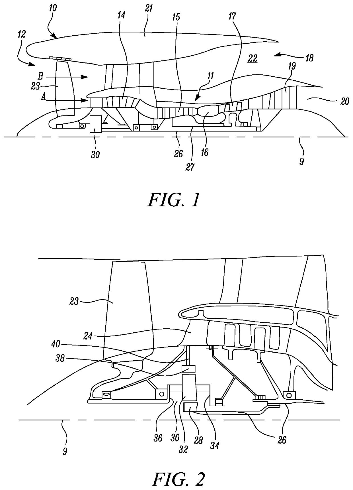
[0071]FIG. 1 illustrates a gas turbine engine 10 having a principal rotational axis 9. The engine 10 comprises an air intake 12 and a propulsive fan 23 that generates two airflows: a core airflow A and a bypass airflow B. The gas turbine engine 10 comprises a core 11 that receives the core airflow A. The engine core 11 comprises, in axial flow series, a low pressure compressor 14, a high-pressure compressor 15, combustion equipment 16, a high-pressure turbine 17, a low pressure turbine 19 and a core exhaust nozzle 20. A nacelle 21 surrounds the gas turbine engine 10 and defines a bypass duct 22 and a bypass exhaust nozzle 18. The bypass airflow B flows through the bypass duct 22. The fan 23 is attached to and driven by the low pressure turbine 19 via a shaft 26 and an epicyclic gearbox 3...


PUM


Abstract

A valve assembly comprising: a fluid flow passage to permit the flow of a fluid through the valve assembly; a valve seat; and an actuator assembly. The actuator assembly comprises: a valve member moveable relative to the valve seat between a first position in which the valve member is at least partially engaged with the valve seat to at least partially block the fluid flow passage, and a second position in which the valve member is remote from the valve seat; an actuator body in a fixed position relative to the valve seat; and a metal bellows that is attached to the valve member and to the actuator body and is disposed within the fluid flow passage. The valve member of the actuator assembly is moveable relative to the actuator body and extends around the actuator body such that the actuator body is disposed within the valve member.

Description

CROSS-REFERENCE TO RELATED APPLICATIONS[0001]This specification is based upon and claims the benefit of priority from United Kingdom patent application number GB 1816365.9 filed on Oct. 8th 2018, the entire contents of which are incorporated herein by reference.BACKGROUNDTechnical Field[0002]The present disclosure relates to a valve assembly, and particularly, although not exclusively, to a valve assembly for use in a gas turbine engine, for example a gas turbine aircraft engine.Description of the Related Art[0003]Typically, some valves define a flow path or passage between moving components. In some examples the two moving components require sealing, e.g. with a moveable valve member. However the performance of such seals can be affected by operational factors including swelling of a seal in fluids, surface roughness of mating or engaging surfaces, lubrication, internal pressure, compression, elasticity, humidity, oxidation (for example at elevated temperatures), exudation (for exa...

Claims


Application Information

Patent Timeline
IPC IPC(8): F16K41/10F16K15/02F16J3/04
CPCF16J3/047F16K41/10F16K15/021F16K31/126F16K31/1266F16K1/126F02C9/18F05D2260/606Y02T50/60F04D27/023F04D27/0215
Inventor MURRAY, CHRISTOPHER A.
Owner ROLLS ROYCE PLC
Why Eureka
Try Eureka