
Current self-checking regulation circuit based on voltage calibration

a voltage calibration and voltage regulation technology, applied in semiconductor lasers, laser details, instruments, etc., to achieve the effect of simplifying the entire process of detecting and regulating curren

Active Publication Date: 2020-03-19
HANGZHOU HONGXIN MICROELECTRONICS TECH CO LTD
View PDF0 Cites 1 Cited by
  • Summary
  • Abstract
  • Description
  • Claims
  • Application Information

AI Technical Summary

Benefits of technology

The invention simplifies the process of detecting and regulating current, without the need to calibrate the ADC beforehand. The current source generates a reference current that remains stable regardless of changes in temperature, and the internal generated current is consistent with the external read current.

Problems solved by technology

However, this solution has the following problems.

Method used


Image

  • Current self-checking regulation circuit based on voltage calibration
  • Current self-checking regulation circuit based on voltage calibration

Examples


Embodiment Construction

[0016]The above and other technical features and advantages of this invention will be clearly and completely described combining with the accompanying drawings hereinafter. Apparently, the described embodiment is merely a part of the embodiments of this invention instead of all the embodiments.

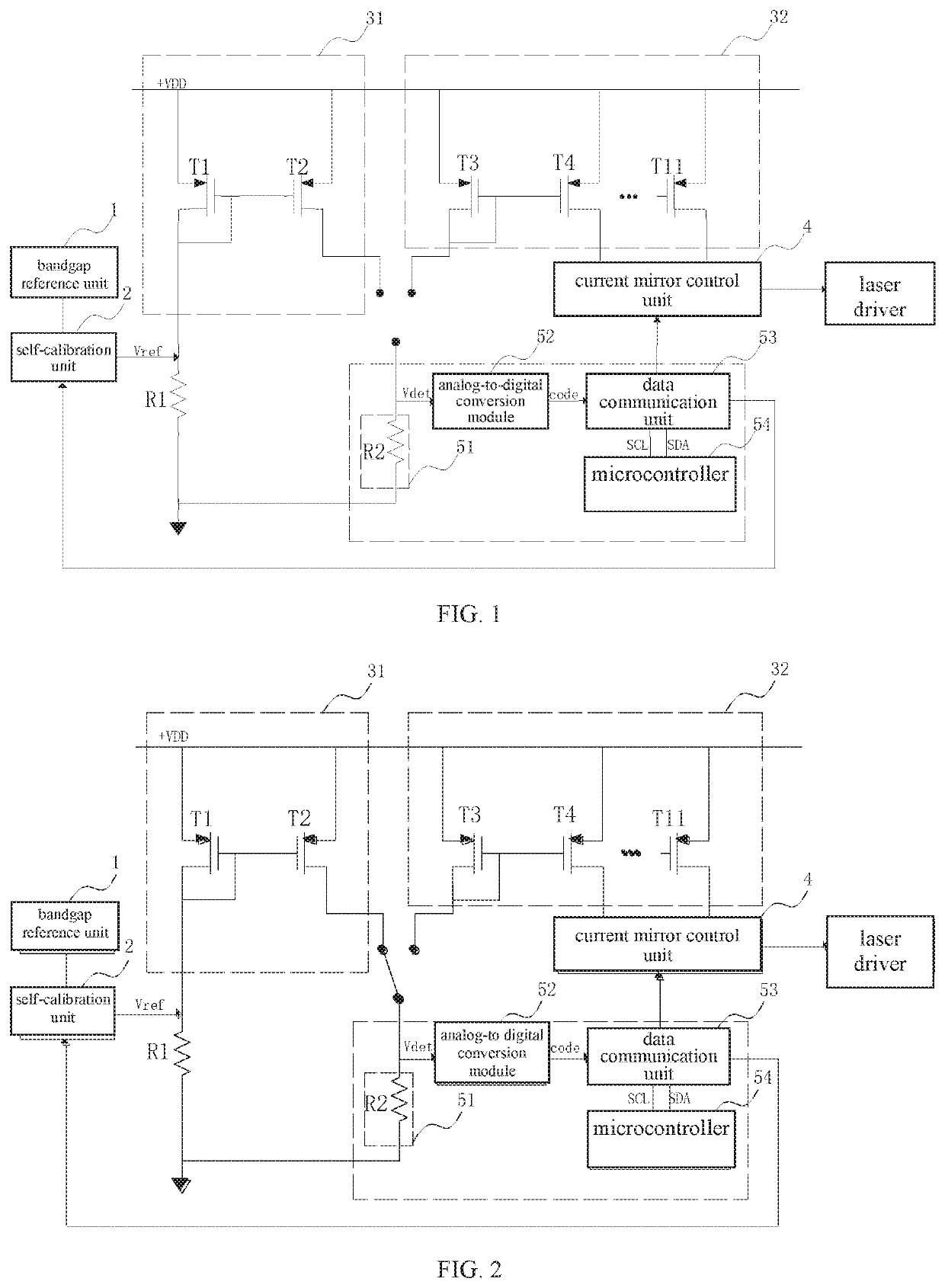
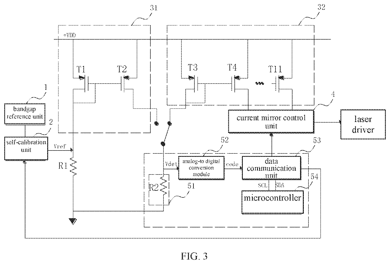
[0017]As shown in FIG. 1, a current self-checking regulation circuit based on voltage calibration, includes a bandgap reference unit 1, a self-calibration unit 2, a detection and regulation unit 5, current mirror units, and a current mirror control unit 4. The number of the current mirror units is at least two, one of the current mirror units is a reference group current mirror unit 31, and the rest of the current mirror units is at least one regulation group current mirror unit 32. The detection and regulation unit 5 is coupled with the bandgap reference unit 1, the reference group current mirror unit 31, the regulation group current mirror unit 32, and the current mirror control unit 4. The ...


PUM


Abstract

This invention provides a current self-checking regulation circuit based on voltage calibration including a bandgap reference unit, a self-calibration unit, a detection and regulation unit, current mirror units, and a current mirror control unit. The bandgap reference unit is configured to generate a voltage signal, the self-calibration unit is configured to respond to a digital signal of the detection and regulation unit and calibrate the voltage signal of the bandgap reference unit. The detection and regulation unit samples the reference current signal and a mirror current signal of the regulation group current mirror unit and generate a digital control signal according to the reference current signal. and the reference group current mirror unit responds to the digital control signal and outputs a regulated bias current signal meeting needs of the laser driver.

Description

CROSS-REFERENCE TO RELATED APPLICATIONS[0001]This Non-provisional application claims priority under 35 U.S.C. § 119(a) on Patent Application No(s). 201811086962.8 filed in People's Republic of China on Sep. 18, 2018, the entire contents of which are hereby incorporated by reference.BACKGROUND OF THE INVENTIONField of the Invention[0002]This invention relates to a technical field of optical fiber communication and, more particularly, to a current self-checking regulation circuit based on voltage calibration.Description of the Related Art[0003]A current drive module in the field of optical fiber communication, such as a vertical cavity surface emitting (VCSEL) laser driver, requires a bias current sources to be stable (not changing with the temperature and process), detectable, and adjustable. Usually, the bias current source is a stable and adjustable 2.5-15 mA current. A solution on the market at present is to add the voltage of an internal bandgap reference source to two ends of an...

Claims


Application Information

Patent Timeline
IPC IPC(8): G05F3/26H01S5/042
CPCH01S5/183G05F3/262H01S5/042G05F1/56G05F1/567H01S5/0427H01S5/06223
Inventor WANG, CHIH-YANGHE, YICHAO
Owner HANGZHOU HONGXIN MICROELECTRONICS TECH CO LTD
Learn More