
Electrode fabrication and design

a technology of electrodes and electrodes, applied in the field of electrode fabrication and design, can solve the problems of degrading the long-term viability and stability of implanted electrodes, complicating the accurate study, diagnosis and/or medical treatment of tissue, and conventional electrodes that cannot be configured to record and/or stimulate with precision at the depths required in some biological applications, and achieves the effect of small feature size and high resolution features

Pending Publication Date: 2020-03-19
NEURALINK CORP
View PDF4 Cites 9 Cited by
  • Summary
  • Abstract
  • Description
  • Claims
  • Application Information

AI Technical Summary

Benefits of technology

The patent describes an improvement to electrode arrays used for recording and stimulating biological tissue. These arrays have better compatibility, can access target tissue deeper within the body, and are more stable and flexible against mechanical strain. The small size and flexibility of the arrays minimize insertion wounds and allow for better contact with target sites, resulting in larger numbers of electrodes being implanted. The arrays can be fabricated using high-resolution techniques, such as stepper lithography, which allows for small feature sizes and large arrays with multiple recording / stimulation channels.

Problems solved by technology

However, during implantation the electrodes can damage or inflame the biological tissue, complicating the accurate study, diagnosis, and / or medical treatment of the tissue.
Moreover, immune response as well as growth of the tissue around the implantation site may degrade the long term viability and stability of implanted electrodes.
In addition, conventional electrodes may not be configured to record and / or stimulate with precision at the depths required in some biological applications.
Further, due to their size and / or material composition, conventional electrodes used in implantable devices may be prone to breakage and may damage biological tissue when they break.
As a result, conventional electrodes may be impractical for use in implantable devices.

Method used


Image

  • Electrode fabrication and design
  • Electrode fabrication and design
  • Electrode fabrication and design

Examples


Embodiment Construction

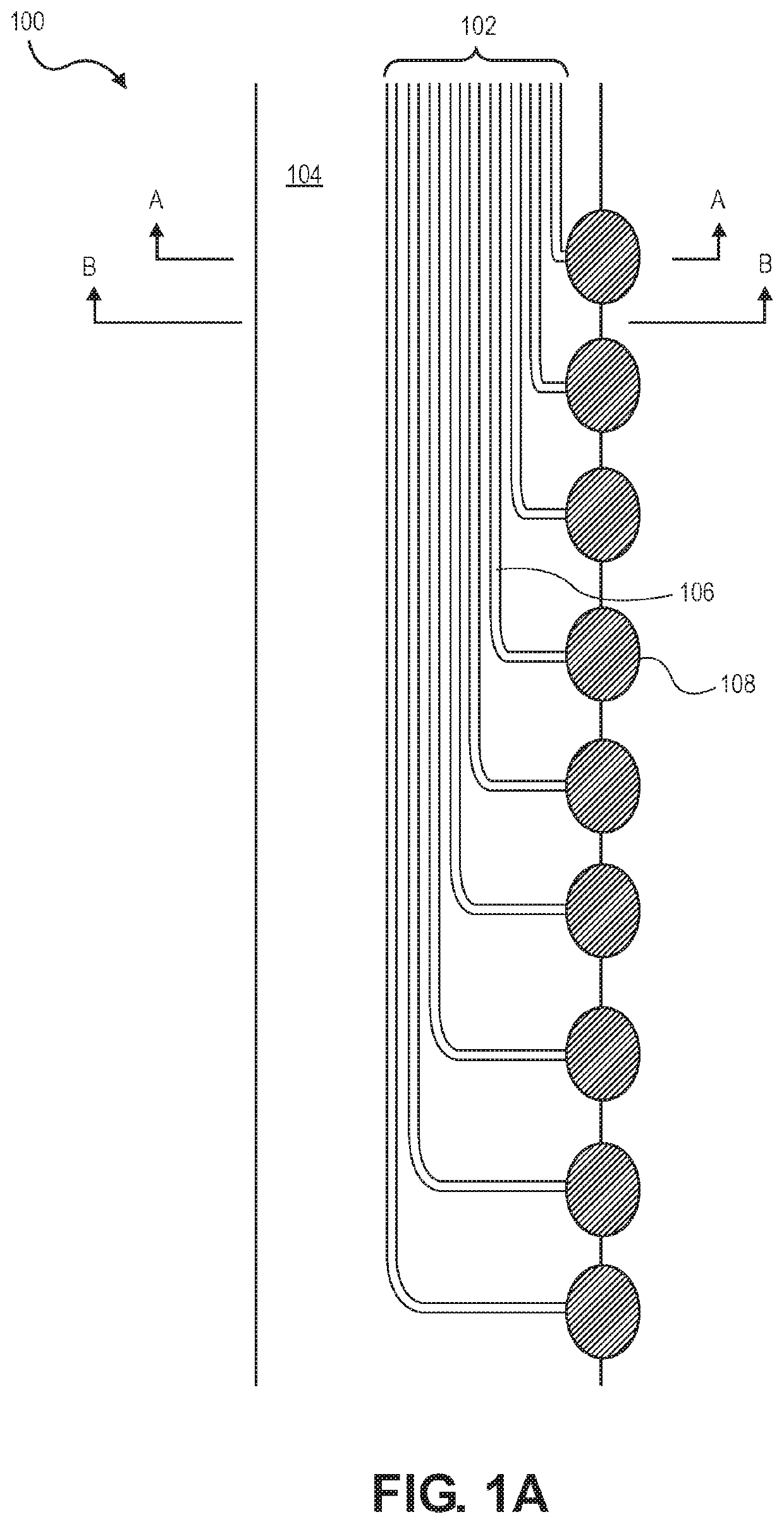
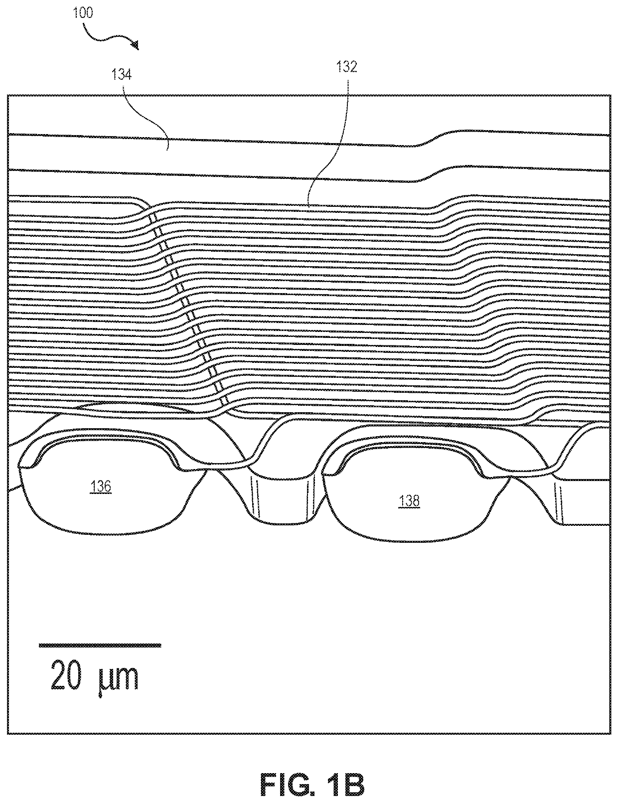
[0057]The present disclosure describes various electrode arrays, which may be included within an implantable device, and methods for fabricating such electrode arrays. The disclosed implantable device may be configured for implantation in biological tissue, including sensitive living tissue, with a single needle insertion via a small insertion hole, yet can provide a plurality of electrodes for recording and / or stimulating electrical signals through such tissue. In particular, embodiments of the disclosed electrode arrays can have a small feature size (e.g., less than 10 micrometers (μm) maximum feature size, or characteristic size of the features fabricated on the contacts) while providing large electrode arrays, with multiple recording / stimulation channels, capable of extending beyond an insertion scar and surrounding a tissue site of interest. The combination of multiple electrode channels and the compliant, branched structure of the arrays allows the system to form detailed ster...


PUM

PropertyMeasurementUnit
areaaaaaaaaaaa
lengthaaaaaaaaaa
lengthaaaaaaaaaa

Abstract

Disclosed are biocompatible multi-electrode devices capable of being implanted in sensitive tissue, such as the brain, and methods for fabricating such arrays. The disclosed arrays can be implanted in living biological tissue with a single needle insertion. The devices can include linear arrays with contacts along an edge, linear arrays with multiple electrodes per opening in a parylene support layer, multi-thread electrode arrays, tree-like electrode arrays, and combinations thereof. In an embodiment, a compliant electrode apparatus can comprise a biocompatible and bio-implantable compliant dielectric having a top edge defined by a top and a side along a length of the dielectric, insulated electrical traces oriented along the length of the dielectric, and electrode contacts coupled to the traces and situated on the side along the length of the dielectric, wherein an exposed portion of a respective electrode contact protrudes beyond the top edge of the dielectric.

Description

CROSS-REFERENCES TO RELATED APPLICATIONS[0001]This application claims the benefit of priority of U.S. Provisional Application No. 62 / 731,496 titled “Electrode Fabrication and Design” and filed on Sep. 14, 2018, which is herein incorporated by reference in its entirety for all purposes.STATEMENT AS TO RIGHTS TO INVENTIONS MADE UNDER FEDERALLY SPONSORED RESEARCH AND DEVELOPMENT[0002]Not ApplicableBACKGROUND[0003]Implantable devices with electrodes can be used for recording and stimulating electrical signals in target biological tissue, such as the brain. However, during implantation the electrodes can damage or inflame the biological tissue, complicating the accurate study, diagnosis, and / or medical treatment of the tissue. Moreover, immune response as well as growth of the tissue around the implantation site may degrade the long term viability and stability of implanted electrodes.[0004]In addition, conventional electrodes may not be configured to record and / or stimulate with precisi...

Claims


Application Information

Patent Timeline
Patent Type & Authority Applications(United States)
IPC IPC(8): A61B5/00
CPCA61B2562/164A61B5/6848A61B2562/125A61B5/6868A61B5/686A61N1/05A61N1/0529A61B5/24A61B5/291A61B2562/043A61B5/293A61B5/263A61N1/3605
Inventor TOLOSA, VANESSA M.TEDOFF, ZACHARY M.HANSON, TIMOTHY L.GARDNER, TIMOTHY J.DIAZ-BOTIA, CAMILO A.CHEN, SUPIN
Owner NEURALINK CORP
Learn More