
Event Triggering in Phased-Array Systems

a phased array and event triggering technology, applied in the field of timing techniques to improve the performance of phasedarray systems, can solve the problems of large source of errors in the locations, poor calibration or insufficient precision of the system, and the inability to respond quickly enough to include near-instantaneous effects, etc., to achieve the effect of improving the intersection

Pending Publication Date: 2020-03-12
ULTRAHAPTICS IP LTD
View PDF19 Cites 12 Cited by
  • Summary
  • Abstract
  • Description
  • Claims
  • Application Information

AI Technical Summary

Benefits of technology

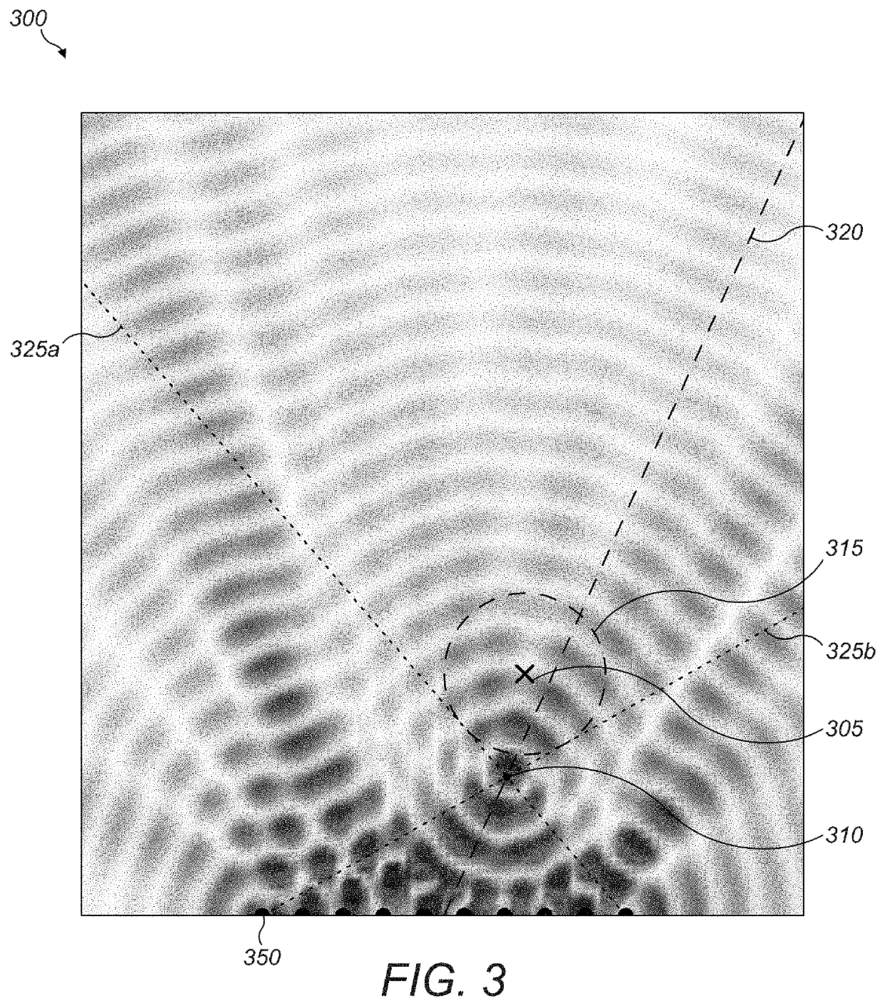
The patent text describes a way to create near-instantaneous effects by breaking down the update process of an array state into parts that depend on different update rates. Alternatively, the method takes advantage of the physical properties of the focusing system to improve the interaction between a body part and a control point in the presence of uncertainty in the tracking system. By focusing behind or in front of the intended region or at a position with a calculated geometric relationship to the intended interaction region, a larger volume of space is addressed which more certainly contains the body part participating in the interaction. This larger volume is then subjected to the ultrasonic radiative energy flux which encodes the desired properties for the interaction point, such as haptic and audio points. Overall, this method allows for faster, more precise interactions to be achieved.

Problems solved by technology

However, the computational requirements of driving the array calculations at a speed necessary to respond quickly enough to include near-instantaneous effects is prohibitive.
These tracking systems may be poorly calibrated or insufficiently precise, creating potentially large sources of error in the locations of the creation of these points.
FIGS. 1 and 4 show that, in some applications, focusing a distribution of sound energy may provide insufficient spatial coverage of the desired regions.
This may be undesirable but might remain serviceable if the redistribution of wave power is small.
If the desired focus radius is significantly larger than w0, z-offset will be large and then the optic approximation becomes less and less reliable.

Method used


Image

  • Event Triggering in Phased-Array Systems
  • Event Triggering in Phased-Array Systems
  • Event Triggering in Phased-Array Systems

Examples


Embodiment Construction

[0015]I. Adding Timed Triggers

[0016]A way to create near-instantaneous effects as described above, is to split the update process of the array state into parts that depend on different update rates. Using this approach, the slow updates that contain individual transducer or array state data that occupy the array for a given period of time are updated through one channel, but discrete ‘triggering’ commands or events that occur or are applied instantly are updated through another. These triggering commands may be time-stamped with the time at which they are intended to be applied and priority queued on the device in a location specifically to quickly determine the next command and apply it. If they refer to a process that occurs in the acoustic field, they may also be applied in a staggered fashion to each transducer so that the effects generated by the command reach the control point simultaneously at the instant in time specified in the time-stamp. Given that these commands are time...


PUM


Abstract

Creating near-instantaneous effects in a phased-array system may occur by splitting the update process of the array state into parts that depend on different update rates. Alternatively, leveraging the uncertainty of physical properties of focusing in a phased-array system may improve the intersection between the body part and the control point. Specifically, by focusing behind or in front of the intended region or at a position with a calculated geometric relationship to the intended interaction region, a larger volume (region) of space is addressed that more certainly contains the body part participating in the interaction. This larger volume is then subjected to the ultrasonic radiative energy flux that encodes the properties desired for the interaction point, which may include haptic and / or audio points.

Description

RELATED APPLICATION[0001]This application claims the benefit of the following U.S. Provisional Patent Applications, which is incorporated by reference in its entirety:[0002]1) Ser. No. 62 / 728,830, filed on Sep. 9, 2018.FIELD OF THE DISCLOSURE[0003]The present disclosure relates generally to improved techniques for using timing techniques to improve performance of phased-array systems.BACKGROUND[0004]A continuous distribution of sound energy, which will be referred to as an “acoustic field”, can be used for a range of applications including parametric audio, haptic feedback in mid-air and the levitation of objects.[0005]By defining one or more control points in space, the acoustic field can be controlled. Each point can be assigned a value equating to a desired amplitude at the control point. A physical set of transducers can then be controlled as a phased-array system to create an acoustic field exhibiting the desired amplitude at the control points.[0006]To create specific dynamic ...

Claims


Application Information

Patent Timeline
IPC IPC(8): G10K11/34
CPCG10K11/34G06F3/016
Inventor KAPPUS, BRIANLONG, BENJAIMIN JOHN OLIVER
Owner ULTRAHAPTICS IP LTD
Learn More