
Fluoroplastic butterfly valve structure

a butterfly valve and fluoroplastic technology, applied in the direction of valve details, valve housings, valve arrangements, etc., can solve the problems of static pressure leakage, short service life, and abraded linings, so as to reduce separation flows, reduce fluid torque, and increase flow amount

Active Publication Date: 2020-03-05
BUENO TECH
View PDF4 Cites 4 Cited by
  • Summary
  • Abstract
  • Description
  • Claims
  • Application Information

AI Technical Summary

Benefits of technology

This patent provides a butterfly disc and a valve body that use a complex sealing means to improve sealing and performance at high temperatures. The goal is to create a more effective and reliable valve structure that can resist high pressure, reduce torque, and withstand temperature variations.

Problems solved by technology

A larger compression ratio results in a greater pressure resistance but causes the lining 93 to become more abraded and have a shorter service life.
If the butterfly disc 92 is not fully closed at a right position, there is a risk that the leakage related to static pressure may be incurred.
When the contact angle 71(θ) of the ribbon sealing is larger, the sliding distance becomes longer, and more materials need to suffer the deformations and the risk of creep.
However, the creep is easily incurred and high torque is required.
These conditions incur the creep easily, require high torque and are unfavorable to the interference sliding 7 while rotating, in particular the service life of the butterfly valve is shortened at high temperatures.
The linear sealing 61 uses a smaller sealing width 63(B), a higher press pressure 64(P), and a larger packing amount 65(ε) to attain a sealing effect capable of resisting high pressure, but the creep is easily incurred and is unfavorable to the temperature resistance.
The portion along the line a-a is easily worn away and causes the creep, which increase the risk of leakage and reduce the service life of the butterfly valve.
The linear sealing 61 cannot provide the performance of the temperature resistance.
The sealing effect of the ribbon sealing is ≤200 psi, so the amount of material deformation is small and the pressure resistance is poor.
The inner surface of the lining having the protuberant trapezoidal cross section and the groove has the sealing to the pressure over 400 psi, but a large amount of material deformation is incurred and the demand for the torque and the service life cannot be fulfilled.
The volume of the material of the protuberant trapezoidal cross section of the tubular portion is too big to prevent the shrinkage after it is subjected to high temperatures.
The back-up ring cannot retain the strength of the structure at high temperatures, so the resistance to high temperatures is greatly decreased.
However, the material of the tubular portion has different thicknesses, the sealing surface uses a thin material structure, and the back-up ring is not fixed by the groove of the valve body.
Because the descriptions are lacking, it is unable to determine whether the temperature at 400° F. and the long-term use of the structure with different thicknesses can fulfill the demand for the pressure resistance and the service life.
The rectangular groove at the outer side of the tubular portion enlarges when the back-up ring expands or becomes deformed, so no support is added to the back-up ring and the strength of the ring cannot be retained.
However, the sealing width and the packing amount are still limited by the size of the O-ring.
No documentary reference can be used to support the effectiveness.
The rubber has high deformation amount and high elasticity but does not have the resistance to corrosion and the resistance to high temperatures.
However, it is obvious that such rubber material structure cannot be adapted to the fluoroplastic material.
If the fluoroplastic is used to make this mountain structure, the creep having the large amount of material deformation in the small area cannot be taken.
This situation causes the encapsulation of the butterfly disc to be ineffective and leads to the infiltration of corrosive liquid.
Accordingly, the packing amount rises shapely and a high amount of deformation and large friction forces are generated.
The fluoroplastic cannot bear the large amount of material deformation in the small area and high friction forces.
The fluoroplastic-encapsulated butterfly disc and the fluoroplastic of the inner surface of the lining suffer high material deformation and the creep, and this situation causes the encapsulation of the butterfly disc to be ineffective and incurs the infiltration of the corrosive liquid.
The fluoroplastic lining needs to design additional shaft sealing surfaces and shaft hole surfaces because the extensive press causes the press surfaces of the fluoroplastic to experience the creep and have wear because of the friction, with the result that the leakage is incurred and the service life of the butterfly valve is reduced.
The inner surface of the lining is a mountain structure, and this structure reduces the area of the flow passage and results in the reduction in the performance of the butterfly valve.
Generally, the rubber material lacks good resistance to high temperatures.
The volume of the material of the fluoroplastic with the projecting trapezoidal cross section is too big, so the strength of the structure cannot be retained under high temperatures and the temperature resistance is greatly decreased.
When the butterfly disc encapsulated by fluoroplastic makes the linear sealing, the creep problem caused by the press sealing and resulting in the large amount of material deformation is not easily incurred.
However, the resistance to high pressure cannot be attained.
The area of the flow passage occupied by the butterfly disc protrusion and the radial connection is large, and this arrangement affects the performance.
However, the sealing performance of the linear sealing is decreased under high temperatures.
The creep problem caused by the press sealing and resulting in the large amount of material deformation is not easily incurred.
Further, the material only provides the less packing amount during the interference sliding operation with friction, which requires a low demand for the torque.
The original spherical surface is retained, but the contact in the extensive area still has wear.
The smaller thickness results in the material deformation easily and causes the inner surface of the lining to shrink inwards easily at high temperatures.
The inward shrinkage of the recessed spherical surface at high temperatures affects the temperature resistance, but the expansion of the rubber of the back-up ring incurred by high temperatures also results in an outward protrusion of the recessed spherical surface, which however decreases the temperature resistance.
However, the structure cannot provide the resistance to high pressure.
The friction is small and the demand for the torque is low.
The thin-layered fluoroplastic of the recessed spherical surface creases easily, becomes abraded and causes the infiltration of the corrosive liquid.
When the fluoroplastic lining is used, the width of the press surface is only 2.5 mm and this condition does not provide the resistance to high temperatures and high pressure.
If it is applied in the butterfly disc having the fluoroplastic encapsulation, the interference sliding results in the material deformation of the fluoroplastic encapsulation and the creep under a high packing amount.
Thus, the temperature resistance and the pressure resistance cannot be attained.
However, the width of the press surface is only 3 mm, so the pressure resistance and the temperature resistance cannot be provided.
Therefore, the current conventional approaches of the fluoroplastic lining butterfly valve cannot fulfill the specifications of the butterfly valve adapted to special purposes, shown as follows:

Method used


Image

  • Fluoroplastic butterfly valve structure
  • Fluoroplastic butterfly valve structure
  • Fluoroplastic butterfly valve structure

Examples


Embodiment Construction

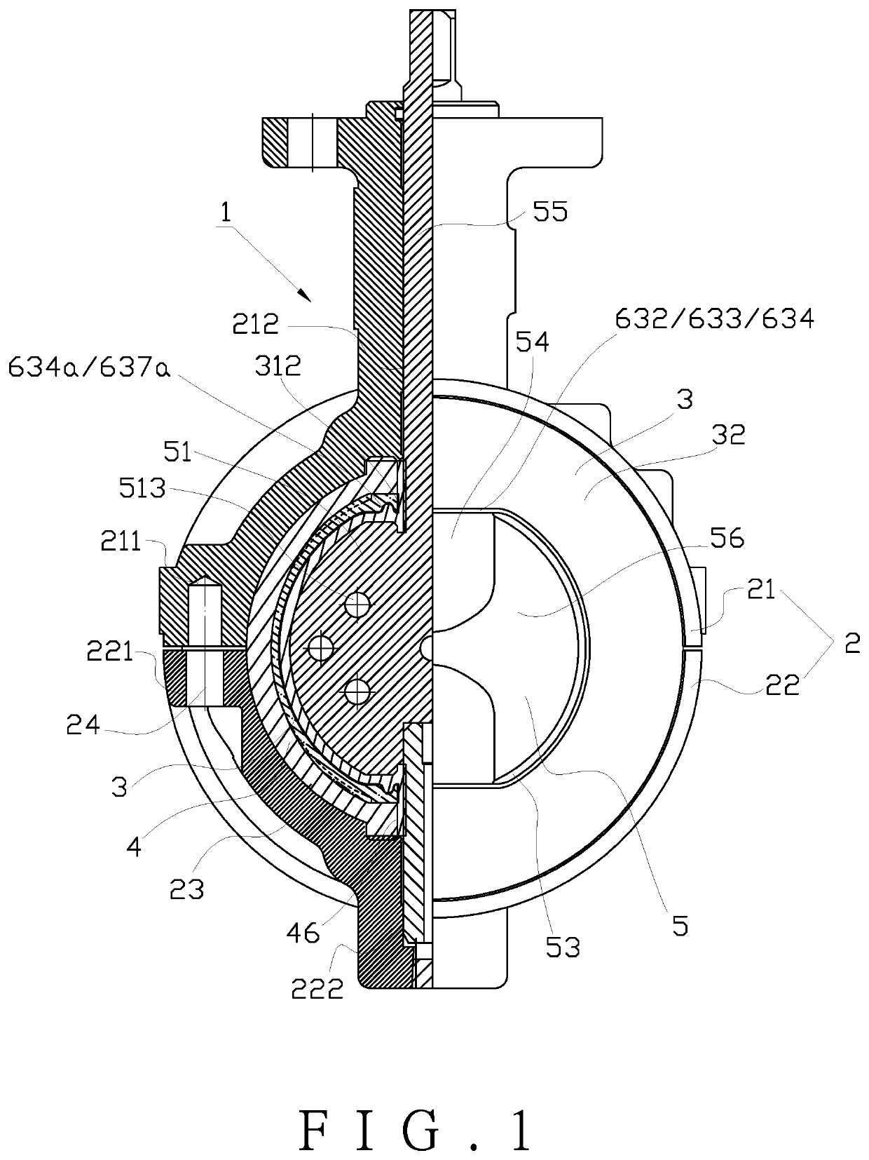
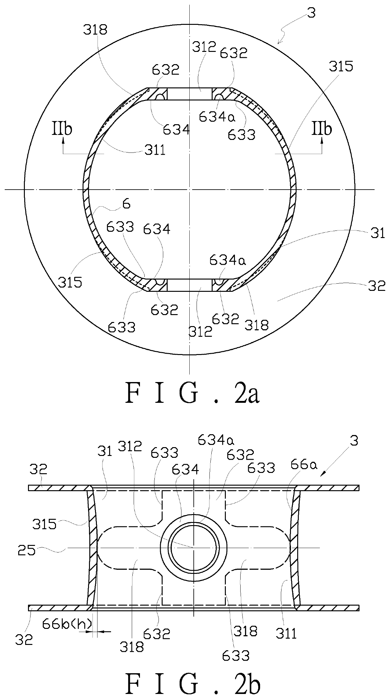
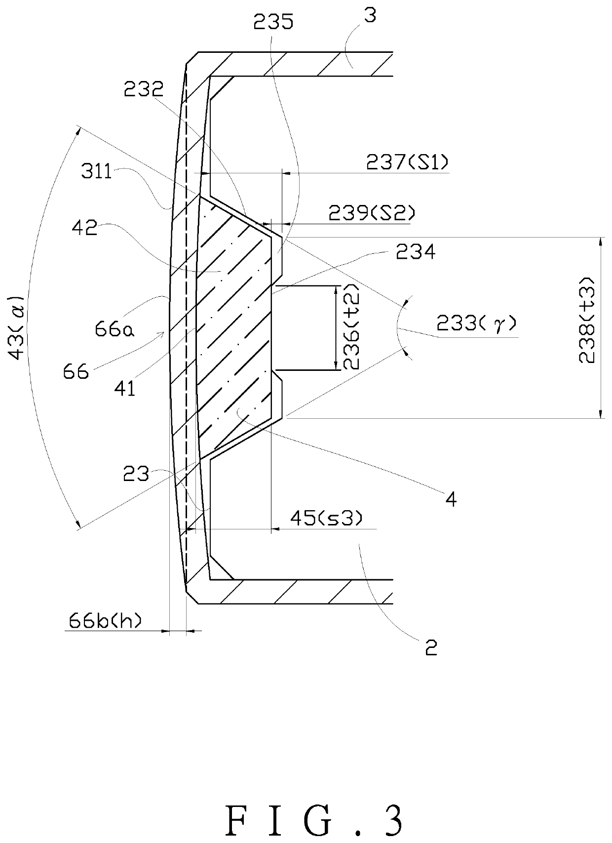
[0183]Referring to FIGS. 1, 2A, 2B, 3, 4A, 4B, 4C and 4D, a fluoroplastic symmetrical butterfly valve 1 includes a valve body 2, a lining 3, a back-up ring 4 and a butterfly disc 5.

[0184]The valve body 2 is formed in a circular ring shape and is horizontally divided into a semicircular-shaped two-piece part, namely an upper valve body 21 and a lower valve body 22. Two fasteners are used to fasten the two valve bodies together to become united. The upper valve body 21 and the lower valve body 22 are installed in an axial direction. The upper valve body 21 has a fastening portion 211 and a shaft hole portion 212 disposed thereon, and the lower valve 22 has a fastening portion 221 and a shaft hole portion 222 disposed thereon. An inner peripheral surface 23 of the valve body 2 is formed to allow an installation of the fluoroplastic lining 3. The inner peripheral surface 23 forms a groove 232 with a trapezoidal cross section which defines an included angle 233(γ), serving to receive the...


PUM


Abstract

The present invention relates to a fluoroplastic butterfly valve structure, including a valve body, a butterfly disc, a lining, and a back-up ring. The butterfly disc has a disc-like structure and includes an inner metallic butterfly disc and an outer fluoroplastic material enclosing the metallic butterfly disc. The butterfly disc is provided with a valve shaft and includes two bulging portions for connecting with the valve shaft. The butterfly disc has a board-like or cone-like cross section. The valve shaft is mounted in a shaft hole portion of the valve body, enabling rotation of the butterfly disc for adjusting flow amount or opening / closing the valve. The back-up ring and the fluoroplastic lining are mounted on an inner peripheral surface of the valve body. An outer rim of the butterfly disc and an inner surface of the lining are tightly pressed against each other by interference fit. The back-up ring is provided between the inner peripheral surface of the valve body and the lining and is made of high temperature resistance rubber in order for bearing the pressing pressure of deformation resulted from said interference fit, thereby meeting the requirement of working with a high-temperature (200 degree Celsius) and high-pressure fluid. The butterfly disc has a complex sealing structure, which includes an unequal-width conical surface and an unequal-width curved surface. The unequal-width curved surface is disposed in a closing direction of the butterfly disc for preventing interference sliding thereof with respect to the inner surface of the lining, thereby reducing deformation of lining and reducing torque. The unequal-width curved surface is composed of arc curves. A portion of the unequal-width curved surface which is at a position near the valve shaft has a longer arc, while a portion of the unequal-width conical surface which is at a position near the valve shaft has a smaller width, said smaller width exceeding 50 percent of a thickness of the outer rim of the inner metallic butterfly disc. Take a 3-inch butterfly disc as an example, where a thickness of the butterfly disc is 8 mm, a sealing width of the butterfly disc is greater than 4 mm. A portion of the unequal-width curved surface which is at a largest-diameter region of a central of the butterfly disc has a shortest arc, while a portion of the unequal-width conical surface which is at the largest-diameter region of the central of the butterfly disc has a largest width, said largest width exceeding 70 percent of the thickness of an outer rim of the inner metallic butterfly disc of the butterfly disc.

Description

BACKGROUND OF THIS INVENTION1. Field of this Invention[0001]This invention relates to a fluoroplastic butterfly valve structure and relates particularly to a symmetrical butterfly valve structure in which a corrosion resistant and temperature resistant fluoroplastic lining is installed. A butterfly disc of the valve structure uses an external fluoroplastic encapsulation to enclose an inner metallic butterfly disc, thereby improving the sealing mechanism of a butterfly disc outer rim, reducing the demand for the torque of a valve shaft, prolonging the service life of the fluoroplastic lining, and increasing the resistance to pressures and temperatures at the time of closing for sealing. The outer rim of the butterfly disc has an interference sliding while closing, and a tight press sealing is attained in a full closed state. Therefore, specifications of the butterfly valve adapted to special purposes can be achieved. For example:[0002]Corrosive liquid: transport fluid, such as hydrof...

Claims


Application Information

Patent Timeline
IPC IPC(8): F16K1/22F16K1/226F16K27/02
CPCF16K27/0218F16K1/222F16K1/226F16K1/224F16K1/2261F16K1/2268F16K1/32F16K1/36F16K1/2265
Inventor CHIEN, HUAN-JANCHEN, PO-WEN
Owner BUENO TECH
Learn More