
Conductive Slip Ring for Logging While Drilling Instrument

a technology of slip ring and logging device, which is applied in the direction of coupling device connection, survey, and well accessories, etc., can solve the problems of high cost, unreliable transmission of electric power and signals, and harsh working environment, and achieves low cost, simple structure, and high reliability.

Active Publication Date: 2020-02-27
INST OF GEOLOGY & GEOPHYSICS CHINESE ACAD OF SCI
View PDF0 Cites 5 Cited by
  • Summary
  • Abstract
  • Description
  • Claims
  • Application Information

AI Technical Summary

Benefits of technology

The technical effect of this patent is to provide a conductive slip ring for logging while drilling (LWD) instrument, which can solve the problems of electric power and signal transmission between two structures with relative rotation in the LWD instrument, such as between the stator and the rotor of the generator, in the rotary steering tool structure, and between the stator and the rotor of the screw drilling tool. The conductive slip ring has a simple structure, low cost, high reliability, and strong temperature, pressure, and vibration resistance abilities. It can be widely applied to various drilling tools and equipment.

Problems solved by technology

When a logging while drilling (LWD) instrument is used in underground work, the working environment is very harsh, and involves high temperature, high pressure, strong vibration, and strong impact; in addition, the LWD instrument has to work in a mud environment.
In such a case, the transmission of electric power and signals becomes a big problem.
Especially, the transmission of electric power and signals becomes extremely unreliable between two structures with relative rotation, and has to be implemented by means of wireless communication techniques or wireless power transmission techniques utilizing electromagnetic waves.
However, wireless communication techniques utilizing electromagnetic waves can only solve the communication problem between instruments, but can't solve the problem of electric power transmission; in addition, the circuit is complex, the cost is high, and the circuit temperature is high, resulting high difficulties.
Wireless electric power transmission techniques have high failure rates in a complex downhole environment, and the efficiency of electric power transmission is limited in a mud environment, an error rate problem exists in signal transmission, the circuit is complex, the cost is high, and the circuit temperature is high, resulting high difficulties.
Therefore, a heretofore unaddressed need exists in the art to address the aforementioned deficiencies and inadequacies.

Method used


Image

  • Conductive Slip Ring for Logging While Drilling Instrument
  • Conductive Slip Ring for Logging While Drilling Instrument

Examples


Embodiment Construction

[0032]Hereunder the technical scheme of the present disclosure will be further detailed with reference to the accompanying drawings.

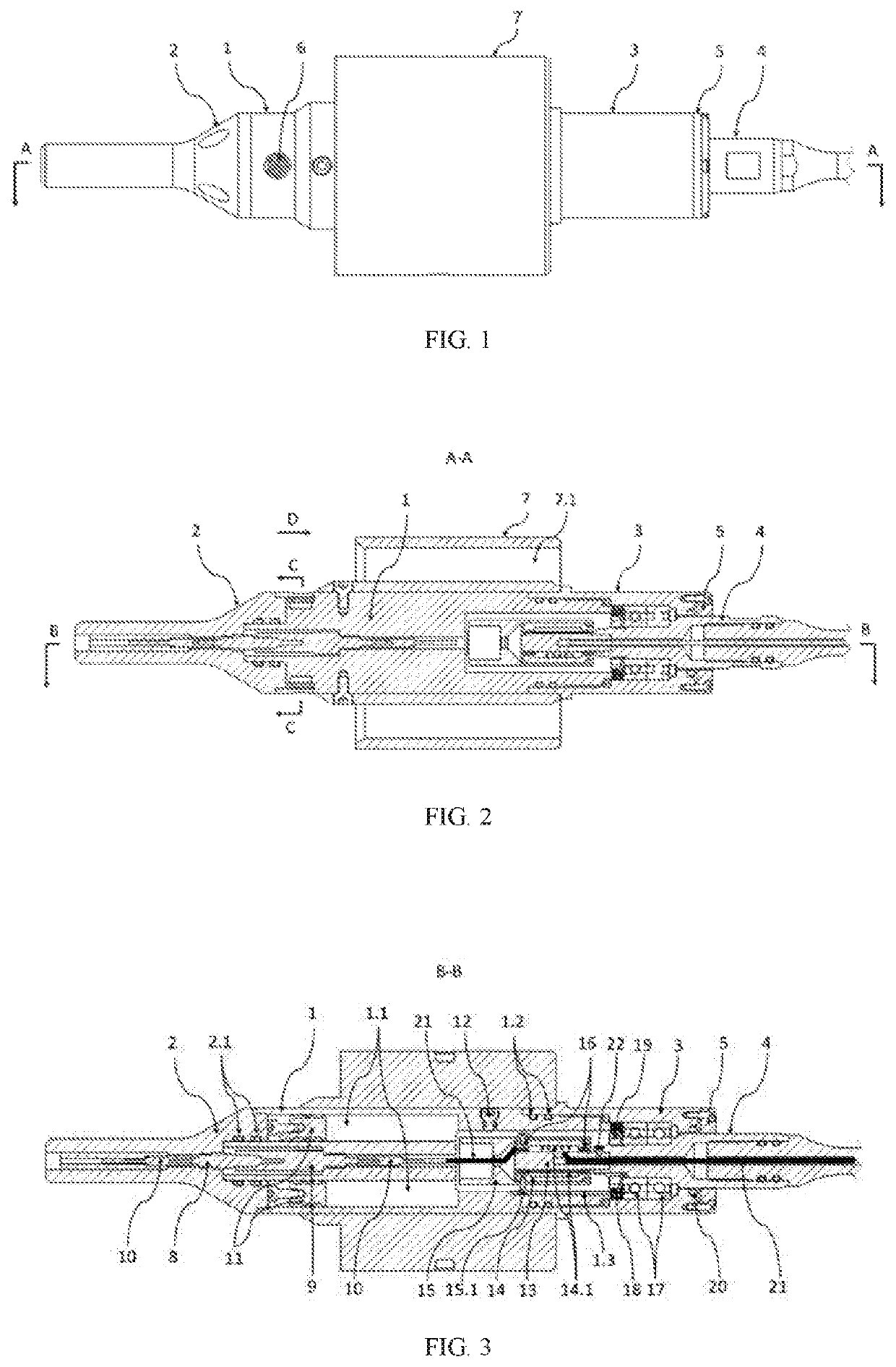
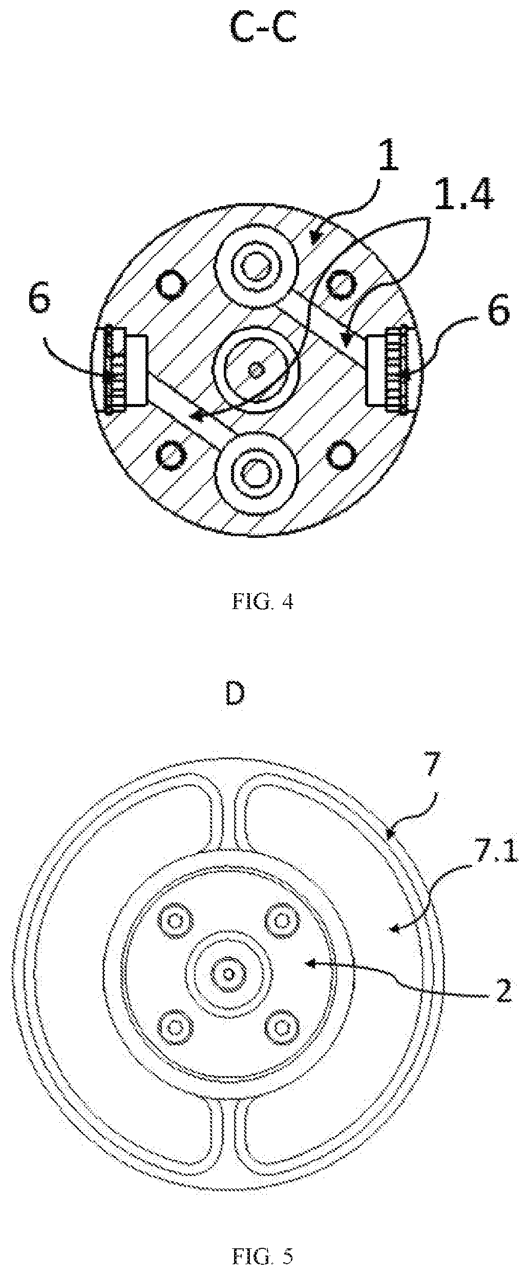
[0033]As shown in FIGS. 1-5, the present disclosure provides a conductive slip ring for logging while drilling (LWD) instrument. The conductive slip ring comprises a housing of slip ring device, a top connector of slip ring, a bottom connector of slip ring, an output shaft of slip ring, an end cap of slip ring, a support body, an inner core system of slip ring, and an electric power and signal transmission device;

[0034]wherein, the housing of slip ring device, the top connector of slip ring, the bottom connector of slip ring, the output shaft of slip ring, and the end cap of slip ring form a sealed cavity together, with high temperature-resistant lubricant fully filled in the sealed cavity,

[0035]the top connector of slip ring is used as an electric power and signal input end or output end,

[0036]the output shaft of slip ring is used as an electric power ...


PUM


Abstract

The present disclosure relates to a conductive slip ring for logging while drilling (LWD) instrument. The present disclosure utilizes a mechanical conductive slip ring to solve the problems of transmission of electric power and signals between two structures that have relative rotation, and the conductive slip ring has a simple structure, doesn't involve any complex circuit, and has low cost and high reliability. With the conductive slip ring in the present disclosure, there is no power transmission efficiency problem or signal transmission error rate problem. The conductive slip ring has high temperature-resistant, pressure-proof, and vibration-roof abilities, and can be applied widely.

Description

CROSS-REFERENCE TO RELATED PATENT APPLICATION[0001]This application is a bypass continuation application of PCT Application No. PCT / CN2018 / 123968. This Application claims priority from PCT Application No. PCT / CN2018 / 123968, filed Dec. 26, 2018, and Chinese Patent Application No. 201810975401.7, filed Aug. 24, 2018, the contents of which are incorporated herein in the entirety by reference.[0002]Some references, which may include patents, patent applications, and various publications, are cited and discussed in the description of the present disclosure. The citation and / or discussion of such references is provided merely to clarify the description of the present disclosure and is not an admission that any such reference is “prior art” to the disclosure described herein. All references cited and discussed in this specification are incorporated herein by reference in their entireties and to the same extent as if each reference was individually incorporated by reference.FIELD OF THE DIS...

Claims


Application Information

Patent Timeline
IPC IPC(8): H01R39/08E21B41/00H01R39/20H01R39/26H01R39/34H02K7/08H02K13/00
CPCH01R39/08H01R39/643H01R39/26H01R39/20E21B49/00H02K7/088H01R39/34H02K13/003E21B41/00H01R39/64E21B47/00H01R13/533E21B47/12
Inventor HE, XINZHENDI, QINGYUNCHEN, WENXUANDU, JIANSHENGLIU, QINGBO
Owner INST OF GEOLOGY & GEOPHYSICS CHINESE ACAD OF SCI
Learn More