Unmanned aerial vehicle and moving object capturing system
a technology of moving objects and unmanned aerial vehicles, which is applied in vehicle position/course/altitude control, process and machine control, instruments, etc., can solve the problem of too expensive airframes to be affordabl
- Summary
- Abstract
- Description
- Claims
- Application Information
AI Technical Summary
Benefits of technology
Problems solved by technology
Method used
Image

Examples
first embodiment
[General Arrangement]
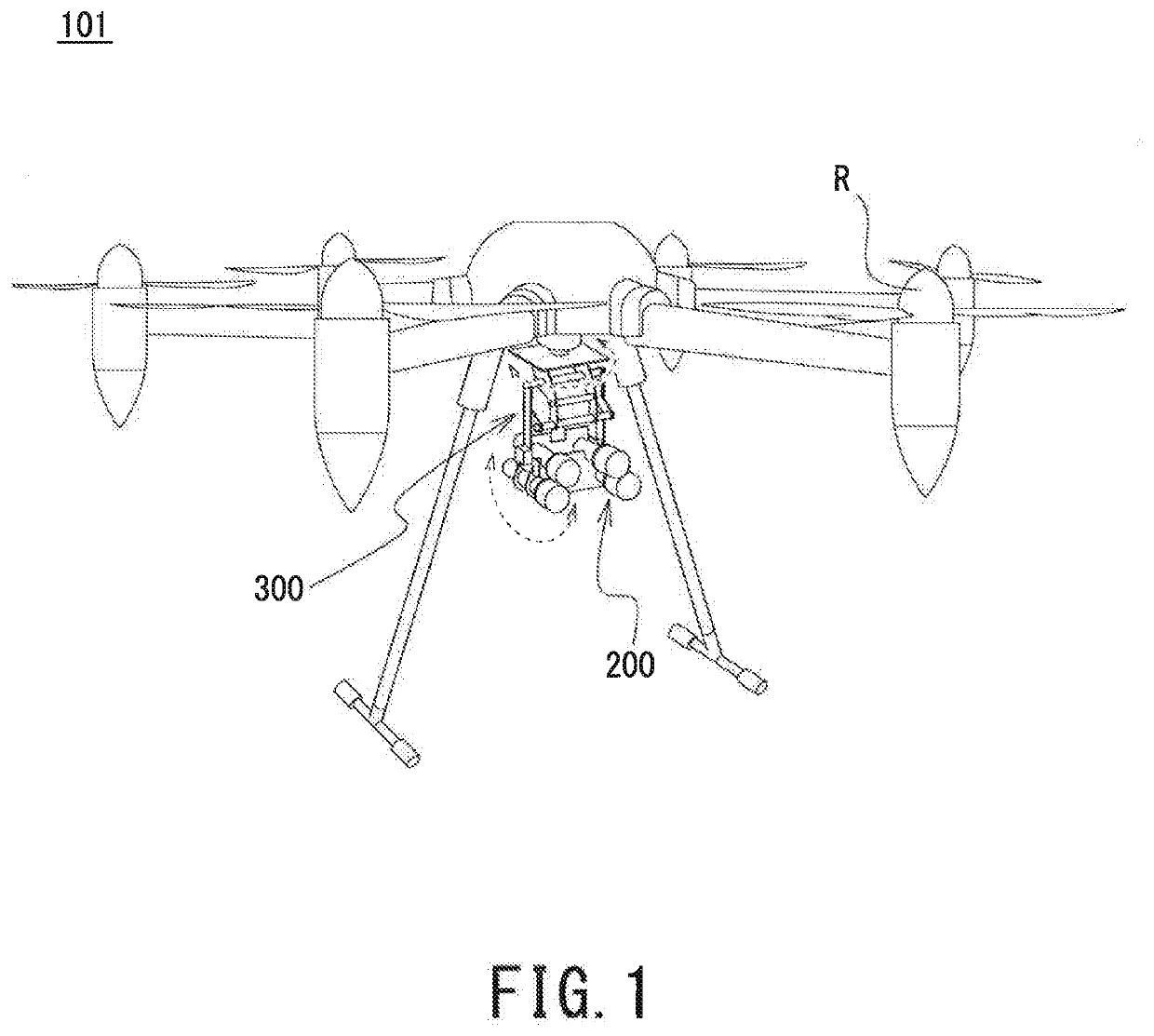
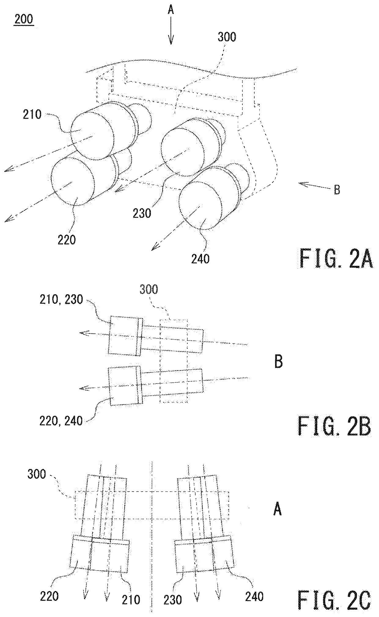
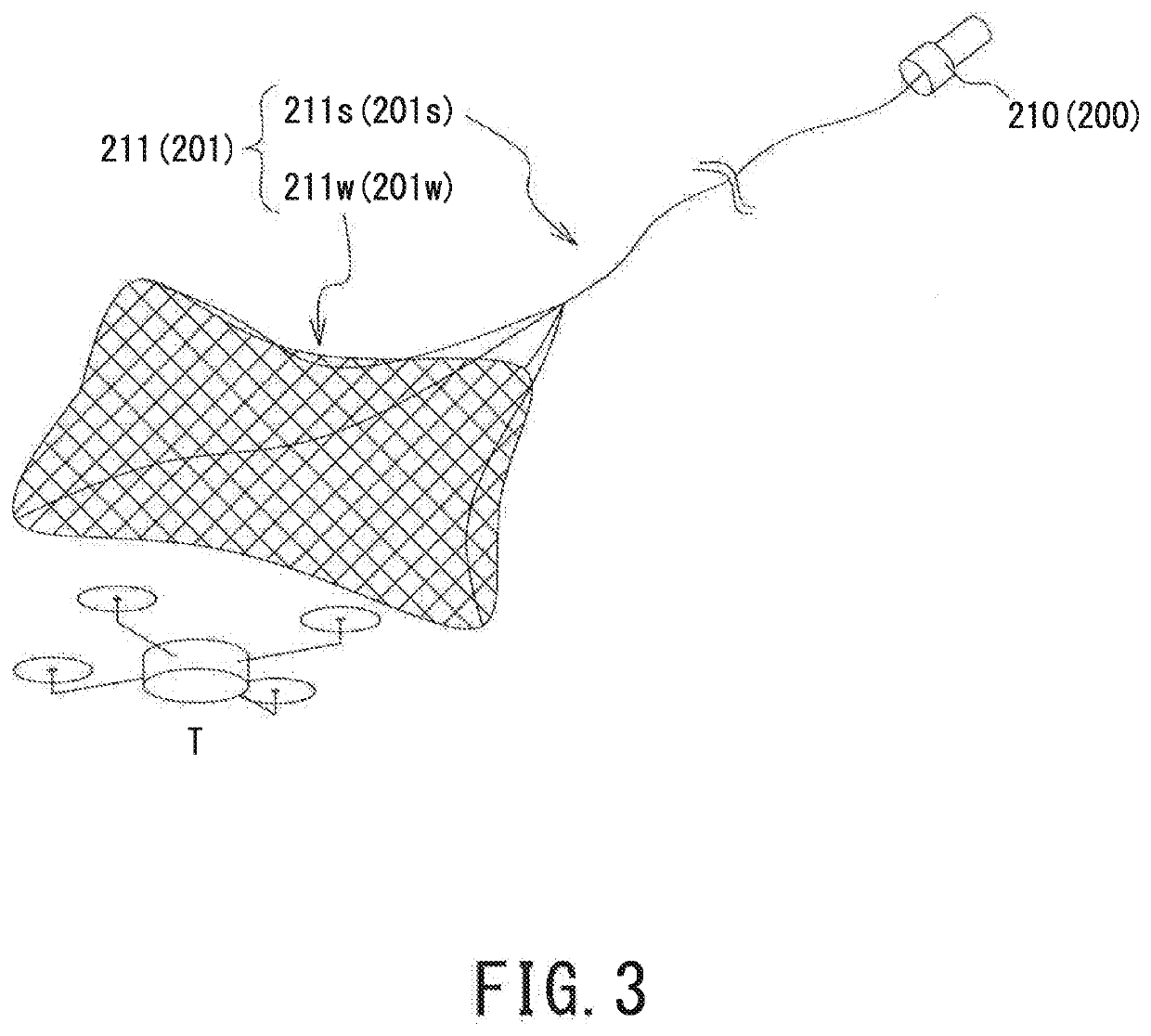
[0053]FIG. 1 is a perspective view of an exterior appearance of a multi-copter 101 according to this embodiment. The multi-copter 101 is an unmanned aerial vehicle equipped with six rotors R arranged at equal intervals in a circumferential direction of the airframe. The multi-copier 101, at a lower portion of the airframe, is connected with a net launcher driver 300. On the net launcher driver 300, a net launcher 200 is arranged. The net launcher 200 includes four net launchers. The net launcher 200 is a capturing net launching device that launches a capturing net to capture the capturing target T. The net launcher driver 300 is a launching direction controller capable of controlling, independently of the direction in which the airframe of the multi-copter 101 is pointed, the aiming direction of the net launcher 200 to change to vertical directions and circumferential directions as seen in FIG. 1.
[0054]The multi-copter 101 according to this embodiment is an unma...
second embodiment
[0074]The second embodiment of the present invention will be described by referring to the accompanying drawings. In the following description, configurations serving identical or similar functions in this and previous embodiment will be denoted the same reference numeral and will not be elaborated further upon here.
[General Arrangement]
[0075]FIG. 5 is a perspective view of an exterior appearance of a multi-copter 102 according to this embodiment. The multi-copter 102 is an unmanned aerial vehicle equipped with six rotors R arranged at equal intervals in a circumferential direction of the airframe. The multi-copter 102, at a lower portion of the airframe, is connected with a net launcher driver 300. On the net launcher driver 300, a net launcher 200 is arranged. The net launcher 200 includes four net launchers. It is to be noted that the number of rotors R may not necessarily be six, similarly to the multi-copter 101 according to the first embodiment.
[0076]Also at the lower portion ...
third embodiment
[0103]The third embodiment of the present invention will be described by referring to the accompanying drawings. In the following description, configurations serving identical or similar functions in this and previous embodiment will be denoted the same reference numeral and will not be elaborated further upon here.
[General Arrangement]
[0104]FIG. 9 is a block diagram illustrating a functional configuration of a moving object capturing system S. FIG. 10 is a schematic outlining the moving object capturing system S. The moving object capturing system S mainly includes: a monitor 500, which monitors an off-limits area; a multi-copter 103, which is an unmanned aerial vehicle; and a server 600, which is an intermediate processor communicable with the monitor 500 and the multi-copter 103. In the following description, the space in the off-limits area that is monitored by the monitor 500 will be referred to as “monitored space M”.
[Configuration of Monitor]
[0105]The monitor 500 includes a p...
PUM
 Abstract
Description
Claims
Application Information
 - R&D
- Intellectual Property
- Life Sciences
- Materials
- Tech Scout
- Unparalleled Data Quality
- Higher Quality Content
- 60% Fewer Hallucinations
Browse by: Latest US Patents, China's latest patents, Technical Efficacy Thesaurus, Application Domain, Technology Topic, Popular Technical Reports.
© 2025 PatSnap. All rights reserved.Legal|Privacy policy|Modern Slavery Act Transparency Statement|Sitemap|About US| Contact US: help@patsnap.com