Fan motor and manufacturing method of the same

a technology of fan motor and manufacturing method, which is applied in the direction of machines/engines, mechanical equipment, liquid fuel engines, etc., can solve the problems of deterioration of the efficiency of the fan motor, and achieve the effects of preventing excessive cutting of polymer, smooth grinding, and reducing costs

Active Publication Date: 2020-02-27
LG ELECTRONICS INC
View PDF0 Cites 2 Cited by
  • Summary
  • Abstract
  • Description
  • Claims
  • Application Information

AI Technical Summary

Benefits of technology

[0037]Further, there is the advantage that since the polymer of the coating layer is soft, the polymer is smoothly ground even if the output of the fan motor is slightly low.
[0038]Further, there is the advantage that since the polymer is a silicon material and the bead is an alumina material, there is no peculiarity of materials, so coating is easy and accordingly cost reduction can be expected.
[0039]Further, there is the advantage that since the hard bead is mixed with the soft polymer in the coating layer, stress that is transmitted into the polymer by the blade can concentrate around the bead and cracks connecting the beads can be formed in the polymer. Accordingly, a portion of the polymer can be cut off along the cracks and excessive cutting-off of the polymer is prevented.
[0040]Further, there is the advantage that since there is the coating layer between the blade and the inner circumferential surface of the shroud, the concern of damage to the inner circumferential surface of the shroud due to contact with the blade is prevented.
[0041]Further, there is the advantage that since the impeller is inserted in the shroud and grinds the coating layer, the manufacturing cost of the fan motor is reduced in comparison to a manufacturing method of precisely machining a coating layer and then inserting an impeller into a shroud.
[0042]Further, there is the advantage that since the second thickness of the second area changes in the inner circumferential direction of the shroud, the gap between the blade and the inner circumference of the blade can be minimized even if the rotational axis of the impeller is eccentric to the virtual center axis of the shroud.

Problems solved by technology

When the tip clearance is too small, the blades or the impeller cover may wear, but when it is too large, excessive leakage flow slides over the tips of the blades, so the efficiency of the fan motor may be deteriorated.

Method used


Image

  • Fan motor and manufacturing method of the same
  • Fan motor and manufacturing method of the same
  • Fan motor and manufacturing method of the same

Examples


Embodiment Construction

[0054]Exemplary embodiments of the present invention will be described in detail hereafter with reference to the accompanying drawings.

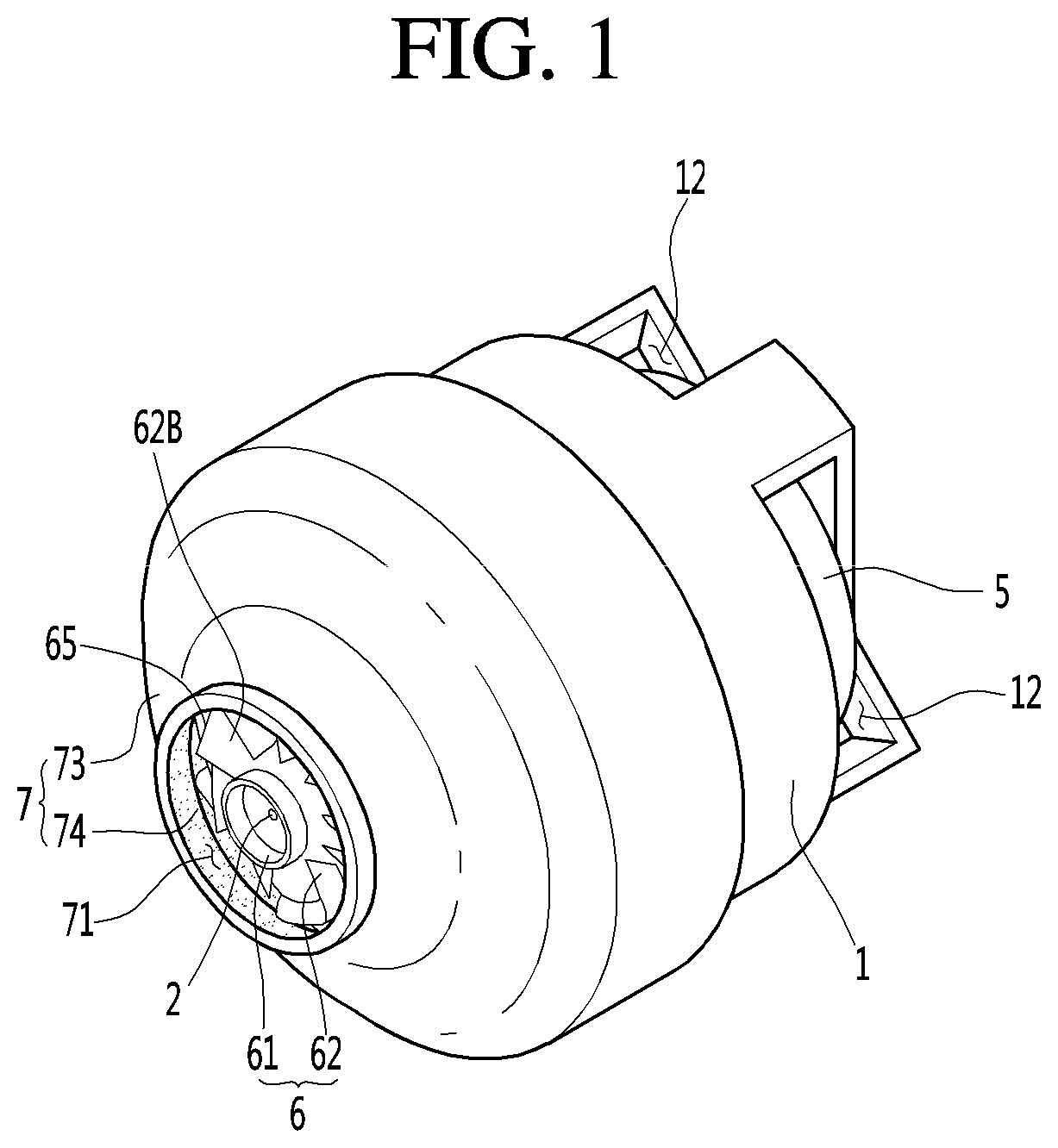
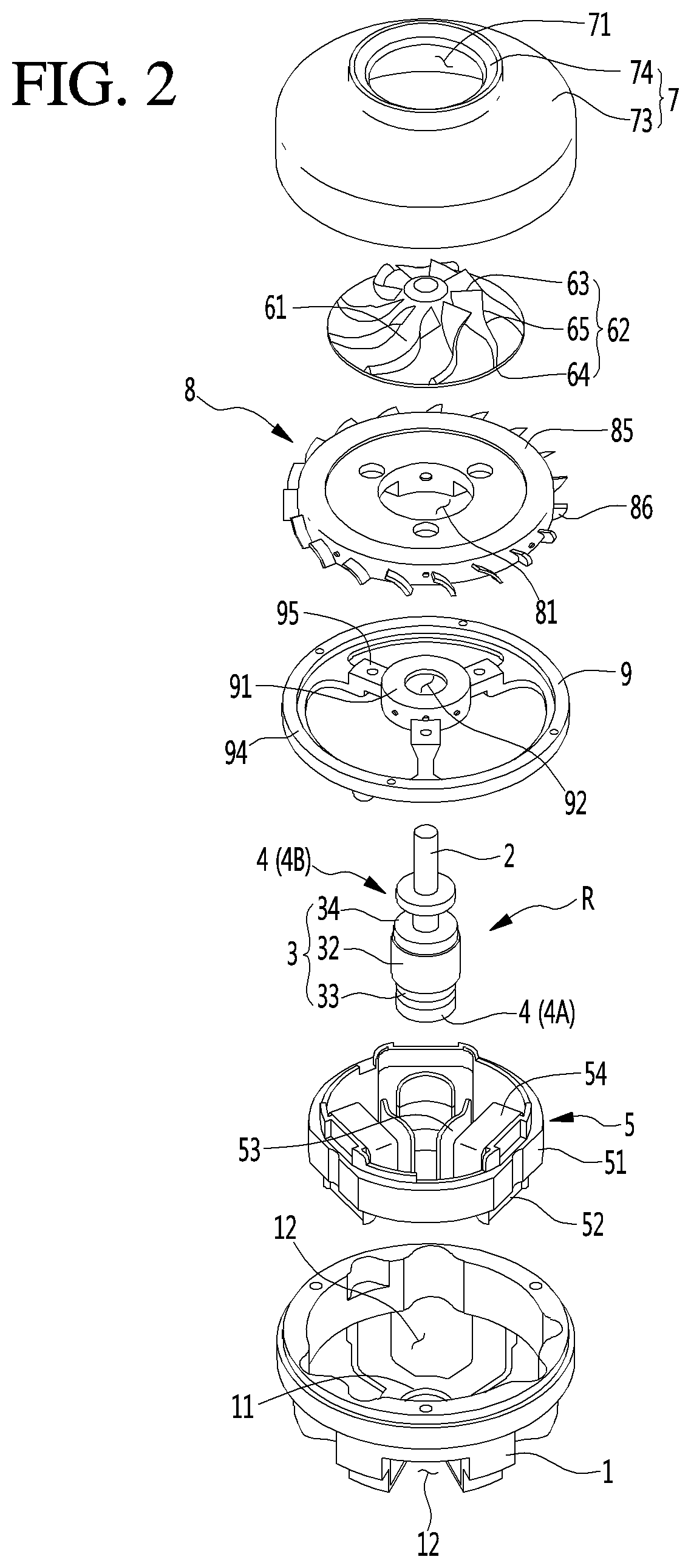
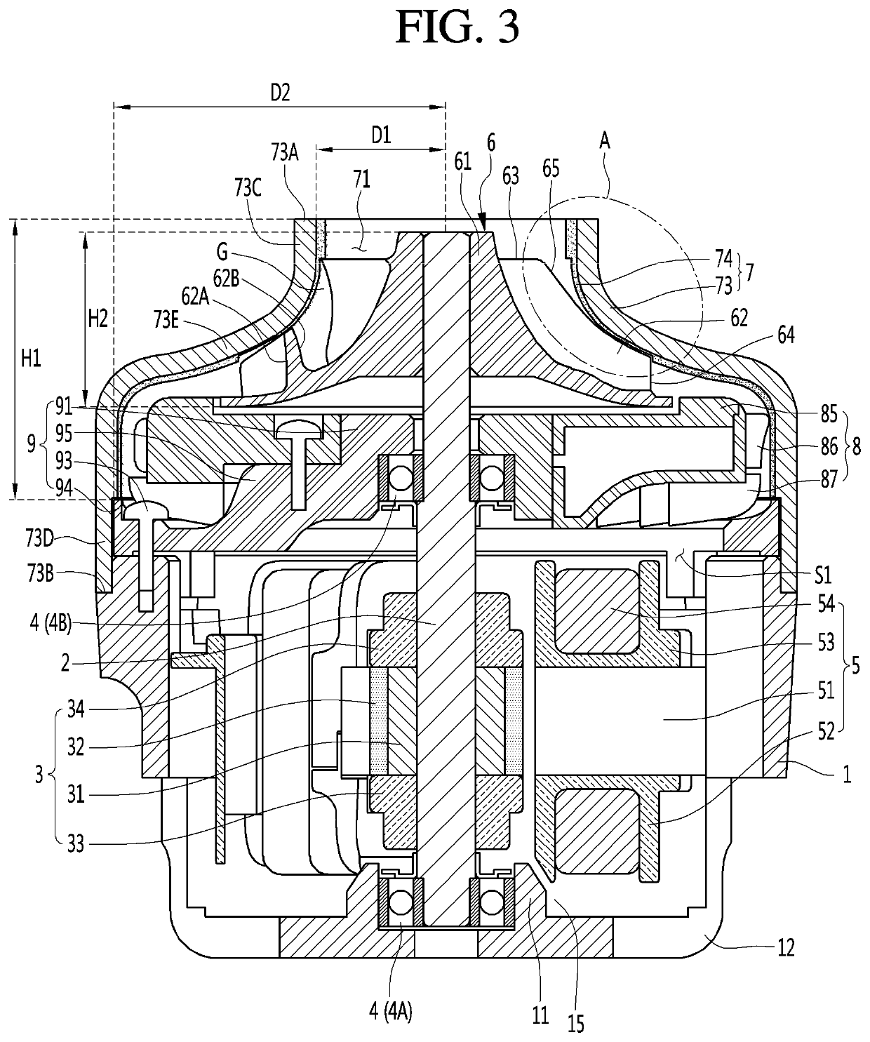
[0055]FIG. 1 is a perspective view of fan motor according to an embodiment of the present invention, FIG. 2 is an exploded perspective view of the fan motor according to an embodiment of the present invention, and FIG. 3 is a cross-sectional view showing the inside of the fan motor according to an embodiment of the present invention.

[0056]A fan motor according to the present embodiment may include: a motor housing 1; a rotary shaft 2, a rotor 3 mounted on the rotary shaft 3; a stator 5 disposed inside the motor housing 1 and surrounding the rotor 3; an impeller 6 connected to the rotary shaft 2; and an impeller cover 7 surrounding the outer circumferential surface of the impeller 6. The impeller cover 7 may include a coating layer 74 for minimizing the gap between the impeller 6 and the impeller cover 7.

[0057]A space S1 where the rotor 3 and the stat...


PUM

PropertyMeasurementUnit
diameteraaaaaaaaaa
stressaaaaaaaaaa
thickness T1aaaaaaaaaa

Abstract

A fan motor according to an embodiment of the present invention may include: an impeller a hub connected to a rotary shaft and at least one blade formed on the outer surface of the hub; a shroud surrounding the outer circumference of the impeller; and a coating layer coated on the inner circumferential surface of the shroud. The coating layer may include: a polymer having strength lower than the strength of the blade; and a plurality of beads mixed with the polymer and having strength higher than the strength of the polymer.

Description

CROSS REFERENCE TO RELATED APPLICATION[0001]The present application claims priority to Korean Patent Application No. 10-2018-0098085, filed on Aug. 22, 2018, the entire contents of which are incorporated herein for all purposes by reference.BACKGROUND OF THE INVENTIONField of the Invention[0002]The present invention relates to a fan motor and a manufacturing method the same and, more particularly, to a fan motor having an impeller cover surrounding the outer circumferential surface of an impeller, and a method of manufacturing the fan motor.Description of the Related Art[0003]A fan motor may be installed in home appliances such as a cleaner, an air conditioner, or a laundry machine, or vehicles and may generate airflow.[0004]When a fan motor is installed in a home appliance such as a cleaner, it may generate a suction force that suctions air first into a dust collector.[0005]Such a fan motor, for example, may include a motor, an impeller connected to the motor, and an impeller cover...

Claims


Application Information

Patent Timeline
Patent Type & Authority Applications(United States)
IPC IPC(8): F01D5/28F04D29/66F04D29/22
CPCF01D5/288F04D29/666F04D29/2222F04D29/4226F04D29/162F04D29/023F05D2230/90F05D2300/611F05D2300/436F05D2300/43F05D2300/20H02K7/14H02K15/00C09D183/04C09D7/61F04D29/526F04D29/622
Inventor KIM, CHANGLAEKIM, BYUNGJIKKIM, SUNGGIHONG, SANGHYUN
Owner LG ELECTRONICS INC
Why Eureka
Try Eureka