
Apparatus and method for measuring precipitation

a precipitation and apparatus technology, applied in the field of devices and methods for measuring precipitation, can solve the problem of erroneously deducing too large raindrops

Pending Publication Date: 2020-02-20
G LUFFT MESS & REGELTECHN
View PDF5 Cites 0 Cited by
  • Summary
  • Abstract
  • Description
  • Claims
  • Application Information

AI Technical Summary

Benefits of technology

The invention is a device that uses a special lens to focus radar waves emitted by an antenna. This allows for accurate and reliable detection of precipitation, while eliminating interference from wind and impact position of raindrops. The device is compact and can be used in a variety of locations, providing highly precise data.

Problems solved by technology

As a result, the measured velocity is also generally higher than the velocity caused by gravity, such that a too large raindrop is erroneously deduced.

Method used


Image

  • Apparatus and method for measuring precipitation
  • Apparatus and method for measuring precipitation

Examples


Embodiment Construction

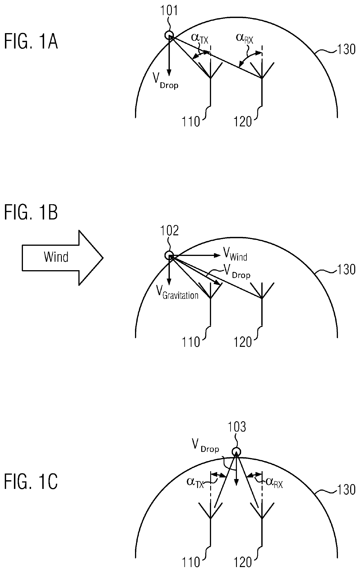
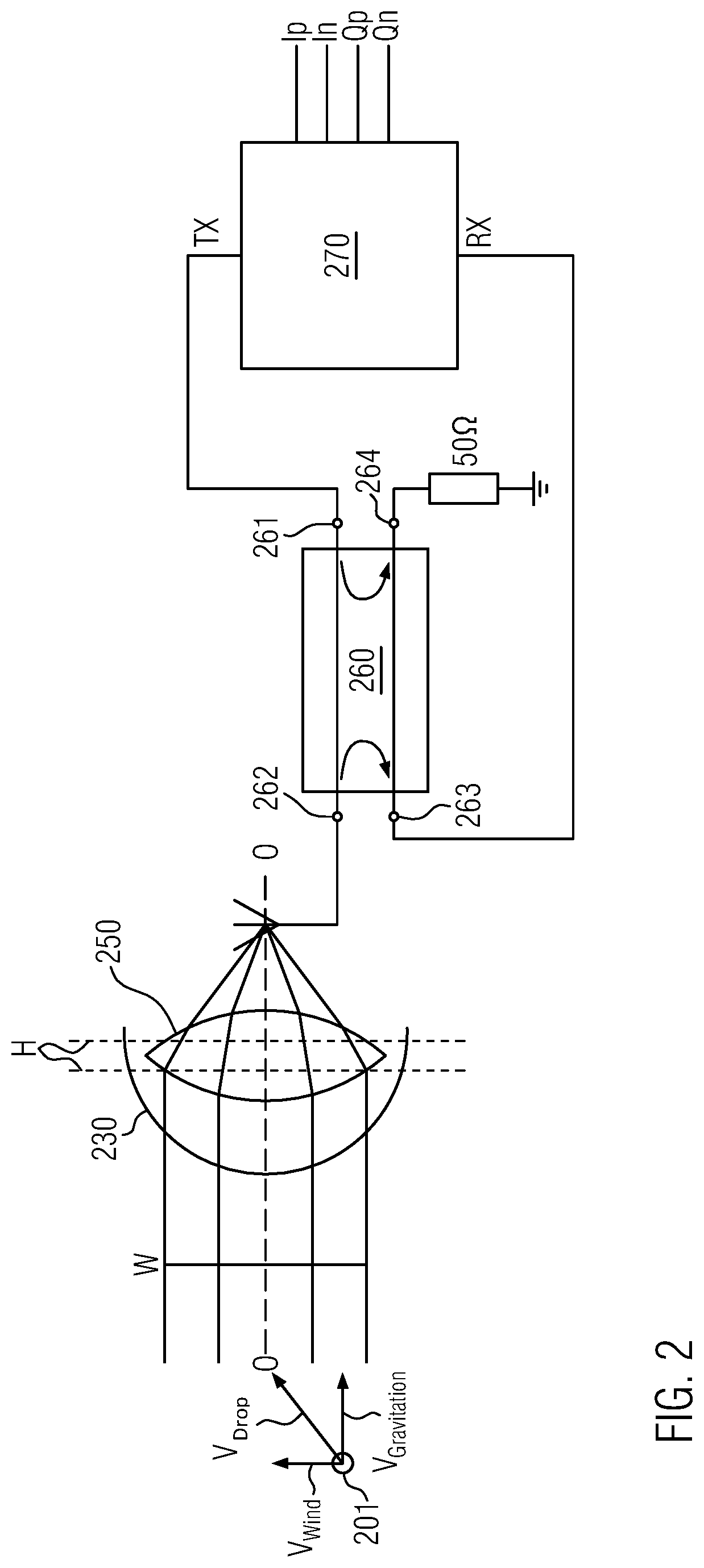
[0010]The above objects are addressed by a device for measuring precipitation by means of radar comprising an antenna adapted to transmit and receive radar waves and a dielectric lens, the antenna being oriented to the dielectric lens such that radar waves radiated from the antenna pass through the dielectric lens. Unlike the bi-static state-of-the-art radars described above, the present invention is a monostatic precipitation radar in which the same antenna is used both to transmit the radar waves, i.e. the primary signals, and to receive the reflected radar waves, i.e. the secondary signals. In particular, the device can have exactly one antenna, which serves simultaneously as transmission and reception antenna.

[0011]Transmission and reception antennas for radar waves are well known in the art and are therefore not described in detail here. It should only be mentioned that the antenna can be designed with a sufficiently large aperture angle in order to have a sufficiently large pa...


PUM


Abstract

This invention provides a device for measuring precipitation by means of radar, comprising an antenna adapted to transmit and receive radar waves and a dielectric lens, the antenna being oriented to the dielectric lens such that radar waves radiated from the antenna pass through the dielectric lens. Furthermore, it is provided a method of determining a velocity of raindrops by radar, comprising the steps of: radiating a radar signal by means of an antenna, receiving a reflected radar signal by said antenna and determining the velocity of the raindrops based on the received reflected radar signal wherein a dielectric lens is disposed in front of the antenna such that the radiated radar signal passes through the dielectric lens.

Description

FIELD OF INVENTION[0001]The invention concerns a device and a method for measuring precipitation.PRIOR ART[0002]Current radar precipitation sensors are based on the principle of a Doppler radar with a separate transmit and receive paths. In the so-called bi-static radar systems, electromagnetic waves in the radio frequency range are transmitted as so-called primary signal bundled together by means of a first antenna. The echoes reflected by objects are then received as a secondary signal by a second antenna spatially separated from the first antenna. From the displacement of the frequency of the reflected signal due to the Doppler effect, the relative movement between the transmitter / receiver system and the objects can then be calculated.[0003]During precipitation measurement, the velocities of raindrops are measured with the aid of such a Doppler radar. Since there is a fixed relationship, i.e. a positive correlation, between the velocity and the diameter of the raindrops, the diam...

Claims


Application Information

Patent Timeline
Patent Type & Authority Applications(United States)
IPC IPC(8): G01S13/95G01S7/41G01S13/58H01Q1/42H01Q19/06H01Q21/06
CPCH01Q1/42G01S13/58H01Q21/065G01S7/415H01Q19/062G01S13/951Y02A90/10
Inventor SCHMITZ-HÜBSCH, AXELTONNIER, MATTHIAS
Owner G LUFFT MESS & REGELTECHN
Learn More