
Devices and Methods to Control Clamping Devices

a clamping device and clamping device technology, applied in the direction of emergency protective circuit arrangement, transistor, etc., can solve the problems of inability to control the clamping device, conventional esd clamping device may exhibit unacceptable current leakage, and the power benefit is negated by intolerable io

Active Publication Date: 2020-01-30
ARM LTD +1
View PDF5 Cites 3 Cited by
  • Summary
  • Abstract
  • Description
  • Claims
  • Application Information

AI Technical Summary

Benefits of technology

The patent text describes an apparatus and method for controlling clamping devices to protect against electrostatic discharge (ESD) in advanced complementary metal-oxide-semiconductor devices. The invention addresses the problem of current leakage in conventional ESD clamping devices, which can cause damage to internal circuitry. The apparatus includes first and second control circuits that are responsive to detection signals and generate drive signals to control the body diode and gate terminal of the clamping device, respectively. The method also includes enabling both control circuits and detecting the presence of transient voltage signals. The technical effect of the invention is to provide effective ESD protection with low current leakage requirements.

Problems solved by technology

Robustness against electrostatic discharge (ESD) is a critical reliability issue in advanced complementary metal-oxide-semiconductor (CMOS) technologies.
The absence of this type of scheme can expose internal core devices in the chip to transient voltage, thus causing catastrophic damage.
However, during normal operation when there is no transient voltage on a supply rail, conventional ESD clamping devices may exhibit unacceptable current leakage due to a larger clamp size as well as inverter current leakage due to rapid response of the ESD clamping device itself.
Nevertheless, any power benefits are negated by intolerable IO leakage partly as a result of the above-described design constraint.

Method used


Image

  • Devices and Methods to Control Clamping Devices
  • Devices and Methods to Control Clamping Devices
  • Devices and Methods to Control Clamping Devices

Examples


Embodiment Construction

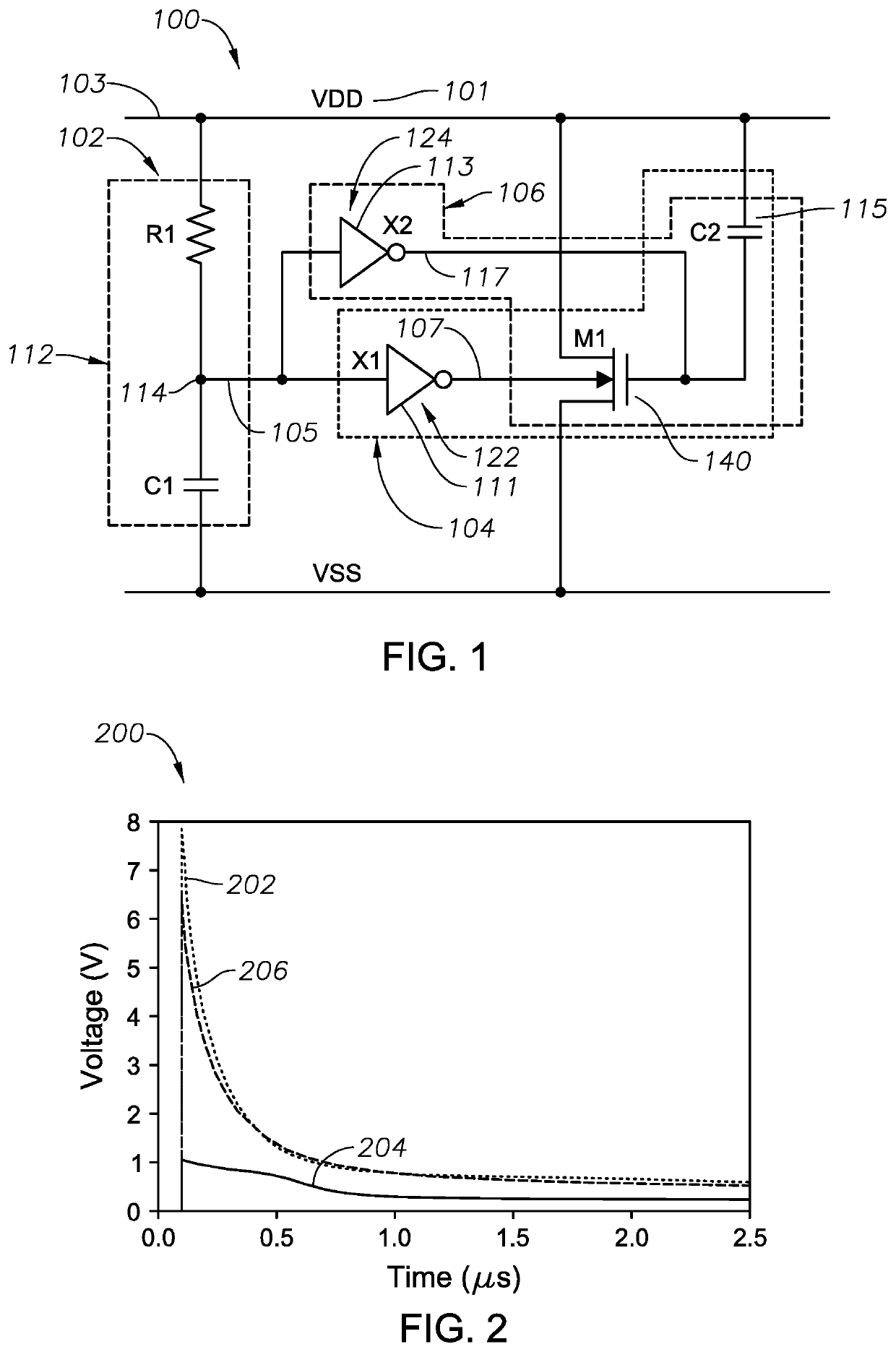
[0015]According to one implementation of the present disclosure, an apparatus to reduce current leakage includes a first control circuit and a second control circuit. The first control circuit is responsive to a detection signal and generates a first drive signal to control a body diode of a clamping device. The second control circuit is responsive to the detection signal and generates a second drive signal to control the gate terminal of the clamping device.

[0016]According to another implementation of the present disclosure, a method includes receiving a detection signal at first and second control circuits. The detection signal indicates a presence of a transient voltage signal. The method also includes enabling the first control circuit that is responsive to the detection signal to control a body diode of a clamping device. The method further includes enabling the second control circuit that is responsive to the detection signal to control the gate terminal of the clamping device...


PUM


Abstract

In a particular implementation, an apparatus to control clamping devices includes a first control circuit and a second control circuit. The first control circuit is responsive to a detection signal and generates a first drive signal to control a body diode of a clamping device. The second control circuit is responsive to the detection signal and generates a second drive signal to control the gate terminal of the clamping device.

Description

STATEMENT AS TO FEDERALLY-SPONSORED RESEARCH[0001]The U.S. Government has certain rights in this invention pursuant to Grant No. HR0011-17-9-0025 awarded by DARPA.FIELD[0002]The present disclosure is generally related to devices and methods to control clamping devices.DESCRIPTION OF RELATED ART[0003]Robustness against electrostatic discharge (ESD) is a critical reliability issue in advanced complementary metal-oxide-semiconductor (CMOS) technologies. In CMOS integrated circuits (ICs), on-chip ESD protection circuits may be used to protect core circuitry from damaging high voltages (such as kV range voltages) caused by ESD events. To prevent circuit damage, ESD clamp circuits are typically incorporated in supply pad library cells and / or input / output (IO) rings (i.e., IO circuits) along the periphery of a semiconductor memory chip.[0004]Conventional ESD clamp protection schemes may utilize a resistor-capacitor (RC) circuit arrangement that may delay the “turn-off” of a clamping device...

Claims


Application Information

Patent Timeline
IPC IPC(8): H01L27/02H02H9/04H02H1/00
CPCH02H9/046H02H1/0007H01L27/0277H01L27/027H01L27/0285
Inventor SAVANTH, PARAMESHWARAPPA ANAND KUMARBLANC, FABRICEBLAAUW, DAVID THEODOREOH, SECHANGLEE, IN HEE
Owner ARM LTD
Learn More