Fuel delivery system

Active Publication Date: 2020-01-30
HAMILTON SUNDSTRAND CORP
View PDF3 Cites 0 Cited by
  • Summary
  • Abstract
  • Description
  • Claims
  • Application Information

AI Technical Summary

Benefits of technology

The patent text states that the filter unit works better at high pressure and the oxygen removal unit works better at low pressure. This means that the filter is designed to work effectively at high pressure, while the oxygen removal unit is designed to work effectively at low pressure. This information may be useful in designing and operating the system that removes oxygen from a gas.

Problems solved by technology

It is not uncommon to see fuel supply temperatures ranging from 350° F. to upwards of 900° F. At such temperatures, the presence of dissolved oxygen is undesirable because the oxygen promotes oxidation reactions that produce undesirable by-products.
Such removal, however, may be further complicated in high pressure fuel systems.

Method used


Image

  • Fuel delivery system

Examples


first embodiment

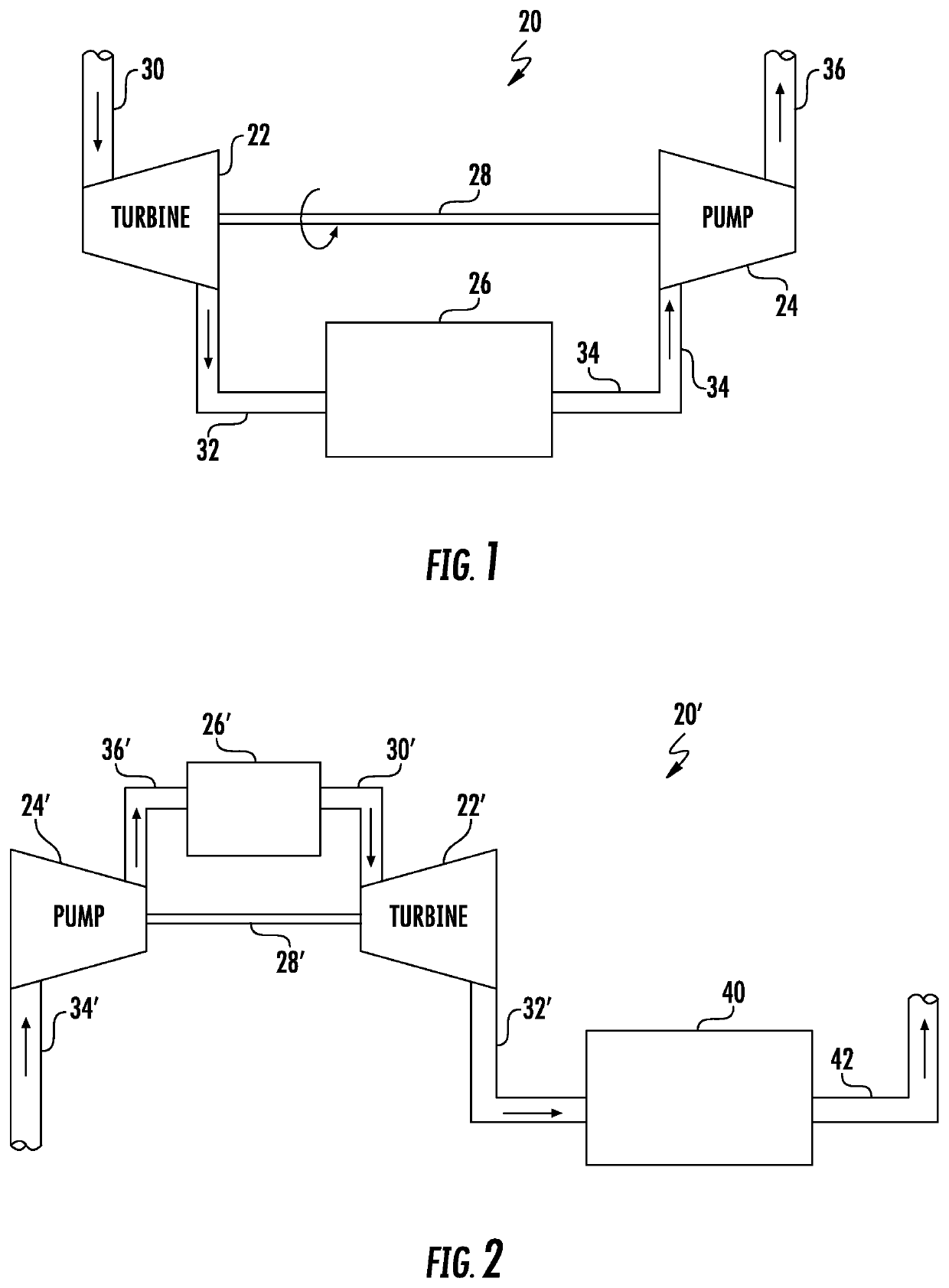
[0029]In this embodiment, the fuel conditioning unit 26′ may a filter unit adapted to filtrate particulates from the fuel. The filter unit 26′ is disposed between and is in fluid communication with the pump outlet conduit 36′ and the turbine inlet conduit 30′. Like the first embodiment, the turbine inlet conduit 30′ and the pump outlet conduit 36′ flow the fuel at a high pressure, and the turbine outlet conduit 32′ and the pump inlet conduit 34′ may flow the fuel at a relatively low fuel pressure.

second embodiment

[0030]Further to this second embodiment, the fuel in the conduits 30′, 32′, 34′, 36′, the pump 24′, the filter unit 26′, and the turbine 22′ is in an oxygenated condition, and the fuel in the oxygen removal unit outlet conduit 42 is in a deoxygenated condition. The term “high pressure” means any pressure or pressure range suitable for effective and efficient operation of the filter unit 26′, and the term “low pressure” means any pressure that is lower than the high pressure and is generally not ideal for proper and efficient operation of the filter unit 26′, but may be optimal for efficient operation of the oxygen removal unit 40.

[0031]Advantages and benefits of the present disclosure include placement of oxygen removal units in high pressure fuel systems where previously not available. Another advantage is the ability to place oxygen removal units in high pressure lines while minimizing the amount of energy loss, and increasing fuel performance as a heatsink. Yet further, the prese...


PUM

PropertyMeasurementUnit
Pressureaaaaaaaaaa
Energyaaaaaaaaaa
Kinetic energyaaaaaaaaaa

Abstract

A fuel delivery system includes a turbine, a pump, and an oxygen removal unit. The turbine is adapted to receive and expel fuel at different pressures. The pump is in fluid communication with, and mechanically coupled to, the turbine, and is configured to expel and receive the fuel at about the respective different pressures. The turbine is configured to convert pressure energy of the fuel to kinetic energy to drive the pump. The oxygen removal unit is in fluid communication with at least one of the turbine and the pump, and is configured to remove oxygen from the fuel.

Description

BACKGROUND[0001]The present disclosure relates to fuel delivery systems, and more particularly to fuel delivery systems capable of fuel conditioning.[0002]Fuel delivery systems typically supply fuel to combustion engines at a prescribed pressure for combustion. The same fuel delivery systems may also function to condition the fuel. Examples of such conditioning may be the filtration and removal of particulate, and / or the removal of oxygen. Whether a filter unit or an oxygen removal unit, each unit may most effectively operate at fuel pressures which are different than the needed, or required, inlet fuel pressure of the combustion engine. Improved means of controlling fuel pressure for optimal performance of various fuel conditioning units is desirable.[0003]In one application, the fuel delivery system may be a jet fuel system, where jet fuel at elevated temperatures and elevated pressures is utilized. In some systems, the fuel is first utilized as a coolant prior to combustion withi...

Claims


Application Information

Patent Timeline
IPC IPC(8): B01D19/00F02C7/22
CPCB01D19/0031F01D15/08F02C7/22F02K9/48F05D2270/11F23K2900/05082B01D2257/104B64D37/34B01D46/00
Inventor O'RORKE, MORGANRAMOS, ERICK
Owner HAMILTON SUNDSTRAND CORP
Why Eureka
Try Eureka