
Laser welding system and method using machined clamping tool

Active Publication Date: 2020-01-09
DUKANE IAS LLC
View PDF0 Cites 0 Cited by
  • Summary
  • Abstract
  • Description
  • Claims
  • Application Information

AI Technical Summary

Benefits of technology

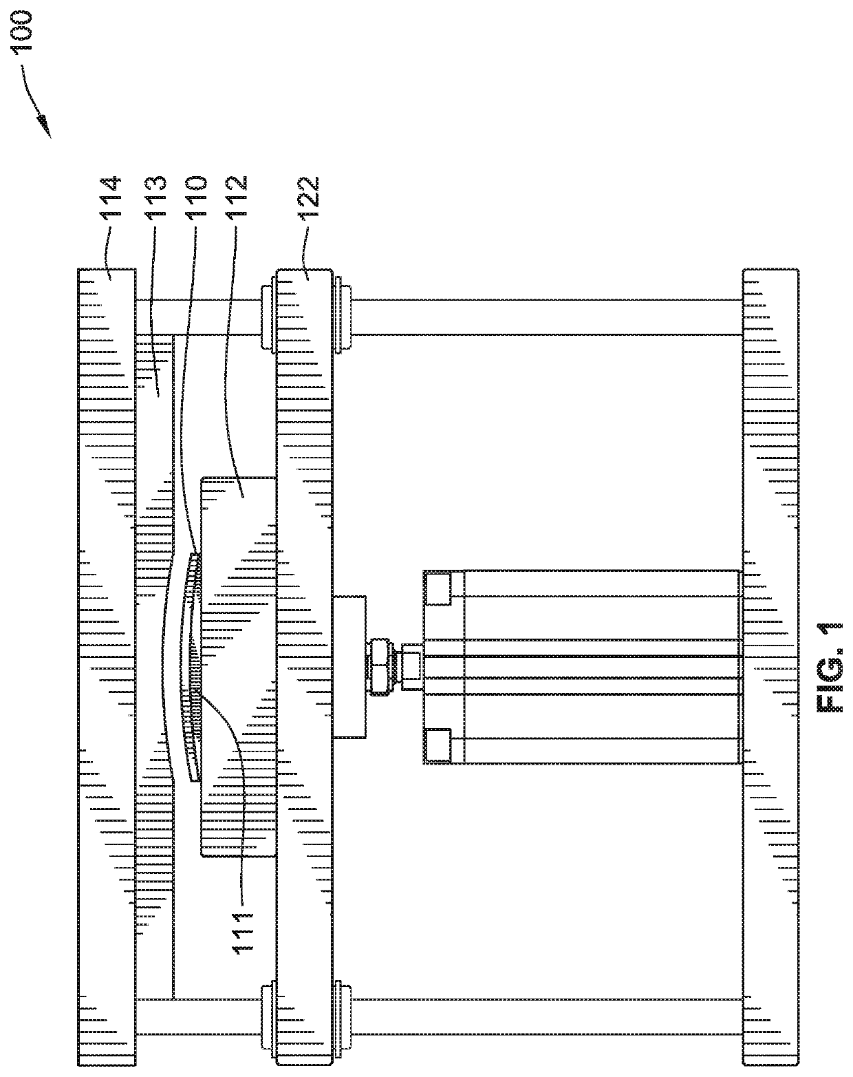
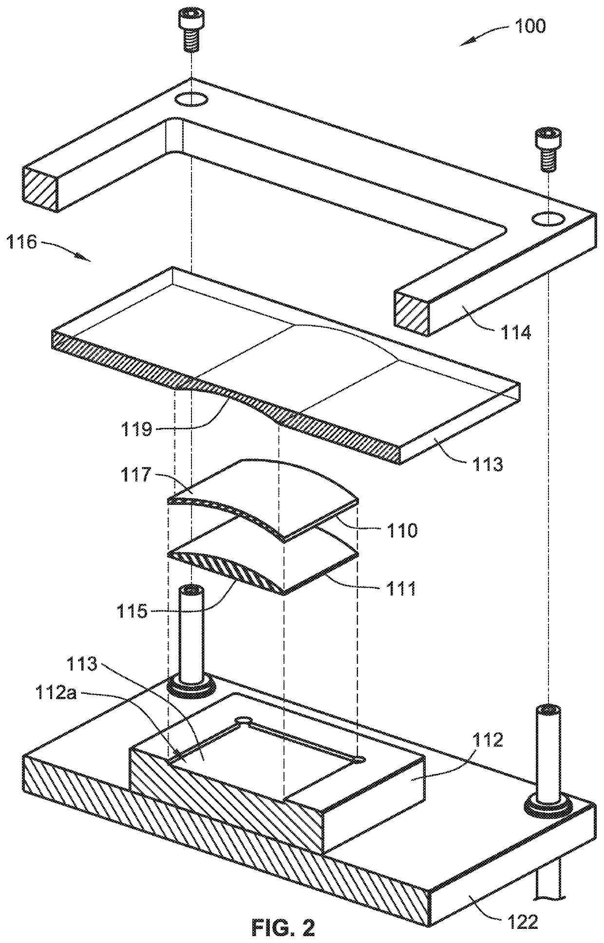
The inventors have done careful research on plastics and through experimentation, found that fluoropolymers like fluorinated ethylene propylene (FEP) meet the requirements of having low power losses when transmitting a laser beam and being able to be processed and machined to conform to an irregular, complex, or non-flat shape. This makes FEP material and other fluoropolymers uniquely suitable for making clamping tools for welding processes utilizing a 2-micron laser.

Problems solved by technology

The clamping requirements and the approaches to address them are essentially the same for both processes (1-micron and 2-micron), however as most plastics absorb laser radiation around the 2-micron laser wavelength, it makes it impossible to use such plastics for clamping the assembly, as such a tool would melt under the laser beam in the same way as the part being welded.
Because it is impossible to transfer clamping force directly onto the welding area in cases when the outer surface is not flat, as using a sheet of glass is not an option, which makes clamping tooling for a 2-micron laser complex and time-consuming to manufacture.

Method used


Image

  • Laser welding system and method using machined clamping tool
  • Laser welding system and method using machined clamping tool
  • Laser welding system and method using machined clamping tool

Examples


Embodiment Construction

[0014]Although the present disclosure will be described in connection with certain preferred embodiments, it will be understood that the present disclosure is not limited to those particular embodiments. On the contrary, the present disclosure is intended to cover all alternatives, modifications and equivalent arrangements as may be included within the spirit and scope of invention as defined by the appended claims.

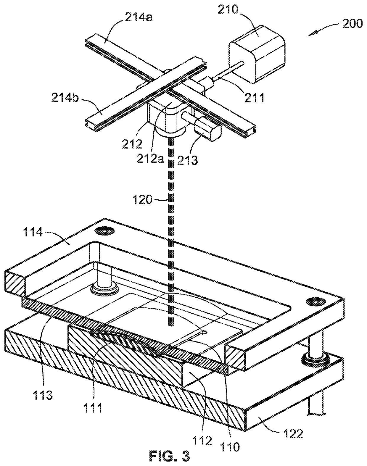
[0015]The laser radiation used in the embodiments disclosed herein can have a wavelength of about 2 microns (e.g., 1940 nm), which is capable of melting thermoplastic materials that do not contain any laser-sensitive additive whatsoever, such as carbon black, to absorb the laser radiation. As used herein, a clamping tool, claiming element, or clamping plate refer to a structure, which is not required to have a flat surface, used for clamping in conjunction with another clamping tool or element or plate. The term plate is not intended to convey that the clamping structure ...


PUM

PropertyMeasurementUnit
Lengthaaaaaaaaaa
Nanoscale particle sizeaaaaaaaaaa

Abstract

A laser welding system for joining first and second thermoplastic workpieces, and including a clamp, an actuator, and a laser source. The clamp includes first and second clamping structures positioned together to engage opposite sides of the workpieces when they adjoin each other. The first clamping structure has a non-flat or irregular surface, facing the first workpiece. The actuator causes the clamping structures to press the first and second workpieces together. The laser source applies laser radiation having a wavelength of 2 microns toward the workpieces to be joined, while they are pressed together by the clamp, to melt irradiated portions of the workpieces to one another. The first clamping structure transmits substantially all of the energy of the laser radiation through the material. The first workpiece has a non-flat or irregular surface facing the first clamping structure, which substantially conforms with the surface of the first clamping structure.

Description

FIELD OF THE INVENTION[0001]The present disclosure relates generally to laser welding of thermoplastic materials and, more particularly, to laser welding that uses laser radiation having a 2-micron wavelength with a fluorinated ethylene propylene clamping tool to weld thermoplastic parts having complex or irregular surfaces to be joined together.BACKGROUND OF THE PRESENT DISCLOSURE[0002]Laser welding uses a laser beam to melt thermoplastic material in a joint area by delivering a controlled amount of energy to a precise location. Systems have been developed for controlling the beam size, and a variety of methods are available for precisely positioning and moving the beam. Laser welding is based on the same basic requirements of material compatibility as other welding techniques, but is often found to be more forgiving of resin chemistry or melt temperature differences than most other plastic welding processes. Nearly all thermoplastics can be welded using a proper laser source and a...

Claims


Application Information

Patent Timeline
IPC IPC(8): B29C65/16B23K26/00B23K26/22B23K37/04B29C65/78B29C65/00
CPCB29K2701/12B23K37/0443B23K2103/42B29C65/1635B29C66/8122B29C65/7841B23K26/22B23K26/0006B23K26/244B23K26/324B23K26/082B29C66/73921B29C66/1122B29C66/301B29C66/81267B29C65/1616B29C65/1654B29C66/8322B29C66/8242B29C66/73366B29C66/81431B29C66/81423B29C66/45B29K2827/12B29K2909/08
Inventor SAVITSKI, ALEXANDERCATHCART, PAUL H.BUGAJ, GRZEGORZ ZDZISLAW
Owner DUKANE IAS LLC
Learn More