
Vehicle drive train and method for operating a drive train

A technology of power train and vehicle, applied in the field of vehicle power train, can solve problems such as hindering the overall efficiency of the power train of the vehicle, and achieve the effect of reducing energy consumption

Inactive Publication Date: 2018-08-03
ZF FRIEDRICHSHAFEN AG
View PDF1 Cites 0 Cited by
  • Summary
  • Abstract
  • Description
  • Claims
  • Application Information

AI Technical Summary

Problems solved by technology

However, this would impede the overall efficiency of the drive train of the vehicle in defined operating ranges in which the respective torque to be transmitted can only be conducted via one of the transmissions, and not to an impermissible extent for this transmission add load

Method used


Image

  • Vehicle drive train and method for operating a drive train

Examples


Embodiment Construction

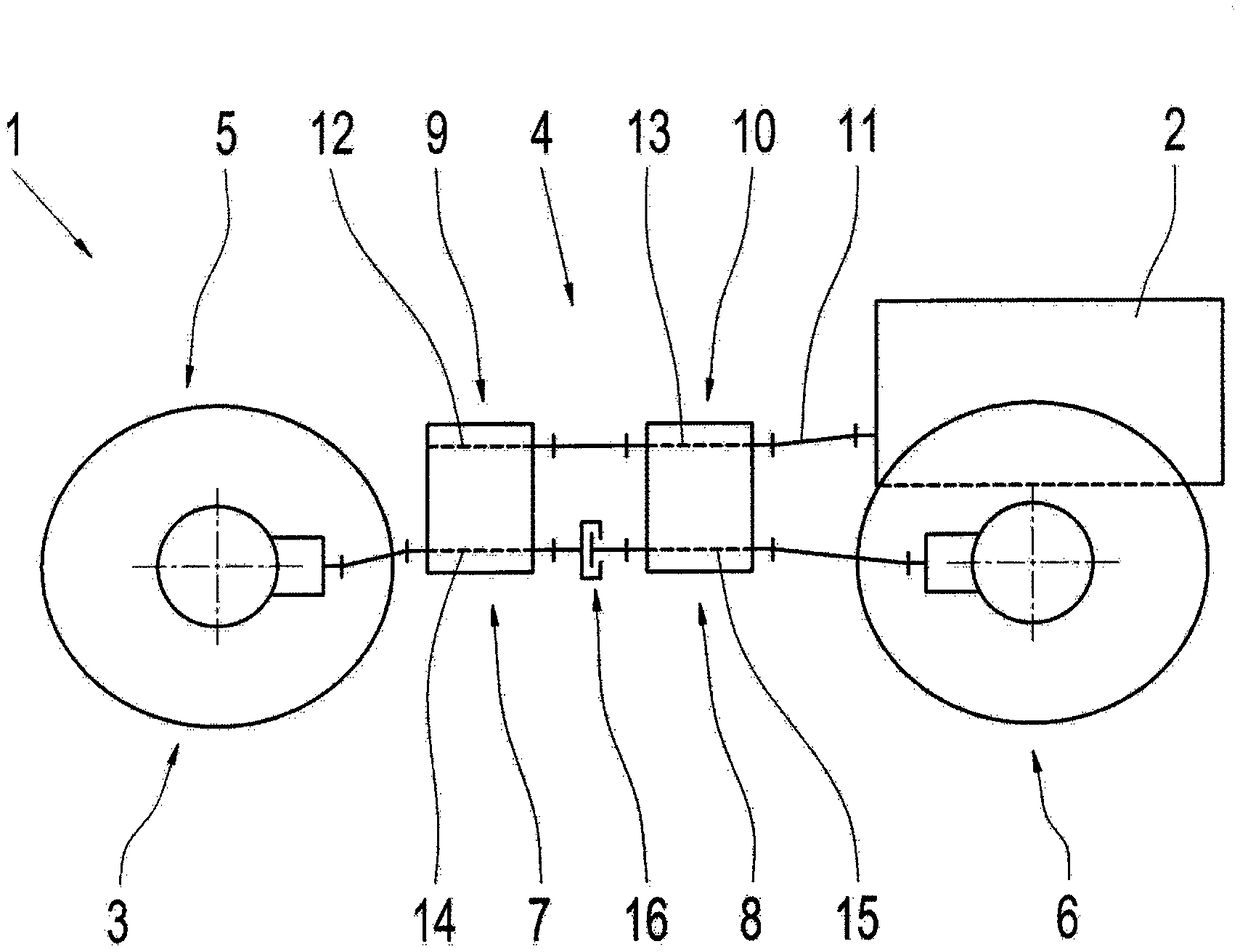
[0030] figure 1 A vehicle drive train 1 is shown in FIG. 1 with a drive machine arrangement 2 , an output mechanism 3 and a transmission arrangement 4 arranged in the power flow between the drive engine arrangement 2 and the output mechanism 3 . The drive engine arrangement 2 is in the present case designed as an internal combustion engine, preferably as a diesel internal combustion engine. Furthermore, it is also possible for the drive engine arrangement 2 to comprise a combination of an internal combustion engine and an electric machine or a plurality of internal combustion engines and / or electric machines in order to be able to provide the respectively required tractive force in the region of the output mechanism 3 . Furthermore, it is also possible for the drive machine arrangement 2 to have one or more electric motors.

[0031] The output mechanism 3 in turn comprises two drivable axles 5 , 6 , wherein the axle 5 is in the present case the vehicle front axle of the vehic...


PUM


Abstract

The invention relates to a vehicle drive train and method for operating a drive train. The vehicle drive-train is equipped with a drive engine, a drive output and a transmission device connected in the power flow between the drive engine and the drive output. The transmission device has at least two transmission units whose transmission ratios can be varied continuously, at least in some ranges, and which are arranged in power-trains running parallel with one another between the drive engine and the drive output. The power-trains can each be functionally connected with a respective axle of thedrive output. At least one shifting element is provided by which the power-trains can be functionally connected in the area between the transmission units and the drivable axles. In addition, a method for operating the vehicle drive-train is described, in which the shifting element is actuated as a function of torque to be transmitted via the transmission device between the drive engine and the drive output.

Description

technical field [0001] The invention relates to a vehicle drive train and a method for operating a vehicle drive train of the type defined in detail in the preamble of claim 1 or 7 . Background technique [0002] A drive train with a drive motor is known from DE 10 2013 019 173 A1, which comprises at least two parallel outputs emanating from the drive motor and at least two transmissions. Each speed changer is respectively connected with a parallel output mechanism. The output mechanisms of at least two transmissions are connected to at least one accumulator transmission. The drive train has at least one differential for the equalization of transmission ratio differences between the transmissions. [0003] The disadvantage here, however, is that the torque to be transmitted between the drive motor of the drive train and the output is routed via the two transmissions over the entire operating range of the drive train. However, this would impede the overall efficiency of th...

Claims


Application Information

Patent Timeline
Patent Type & Authority Applications(China)
IPC IPC(8): B60K17/04B60K17/34
CPCB60K17/04B60K17/34B60K17/06B60K17/08B60K17/344B60K17/346B60K17/3462B60K17/3467B60K17/348B60Y2400/72B60Y2300/84B60K17/10F16H39/04F16H59/14F16H59/50F16H61/4017F16H2059/147F16H2059/506
Inventor 沃尔夫冈·雷布霍尔茨于尔根·莱格纳
Owner ZF FRIEDRICHSHAFEN AG
Learn More