
Control system and control method for vehicle

a control system and control method technology, applied in the direction of mechanical actuators, clutches, mechanical apparatus, etc., can solve the problems of increased engine load caused by drag torque, reduced vehicle starting performance, and increased drag torque, so as to reduce the delay in response or eliminate the delay. , the effect of low durability

Active Publication Date: 2021-10-12
TOYOTA JIDOSHA KK
View PDF3 Cites 0 Cited by
  • Summary
  • Abstract
  • Description
  • Claims
  • Application Information

AI Technical Summary

Benefits of technology

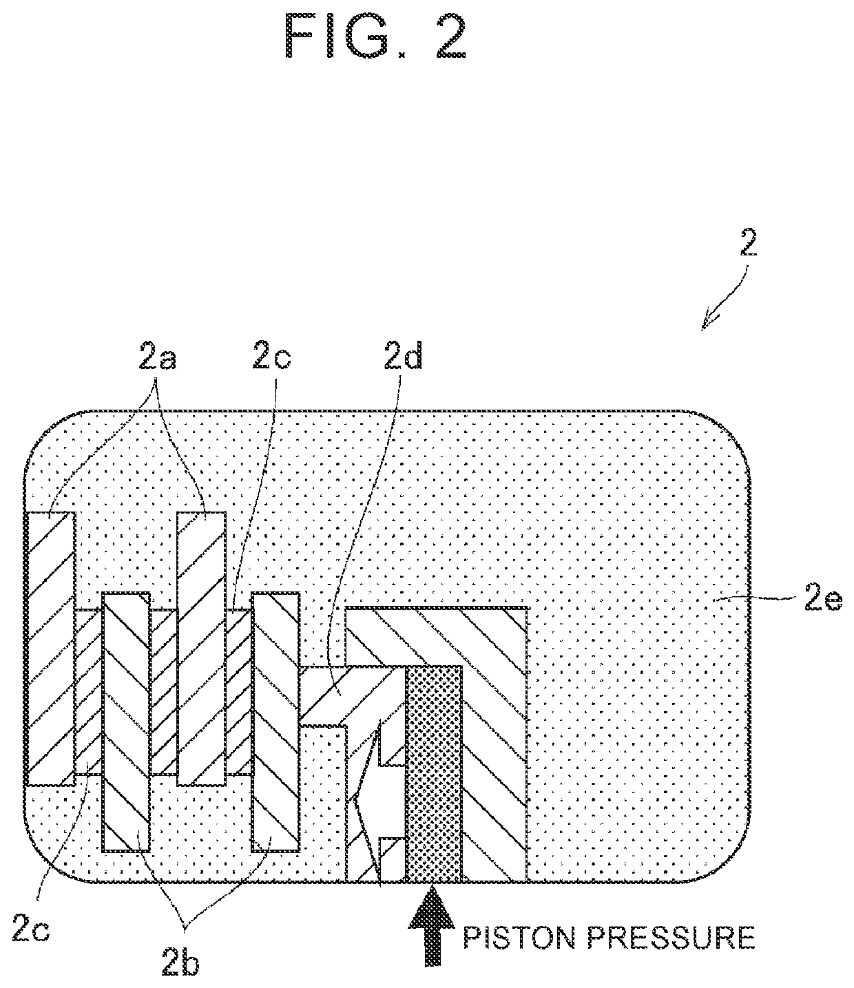
[0006]As known in the art, when a wet clutch is in a half-slipping state or slip engaging state, in a transient period of power transmission, for example, drag torque is inevitably generated due to resistance to sliding between the friction material of the clutch and the oil. Thus, when the wet clutch is used as the starting device, the load of the engine caused by the drag torque is increased. In particular, when the vehicle is started, under a condition where the vehicle is left in a soaked state for a long period of time, or the viscosity of the oil is high at an extremely low temperature, the drag torque becomes extremely large, and the starting performance of the vehicle may deteriorate. In this case, as in the control system described in JP 2018-159419 A, the first clutch having relatively large drag torque is fully engaged in advance, and the vehicle is started using the second clutch having relatively small drag torque, so that the acceleration performance is less likely or unlikely to be deteriorated.
[0008]This disclosure provides control system and control method for a vehicle equipped with two or more wet clutches including a wet clutch as a starting device and a wet clutch that transmits and cuts off power in an automatic transmission, which system and method can curb reduction of the durability of the clutches, while assuring good starting performance.
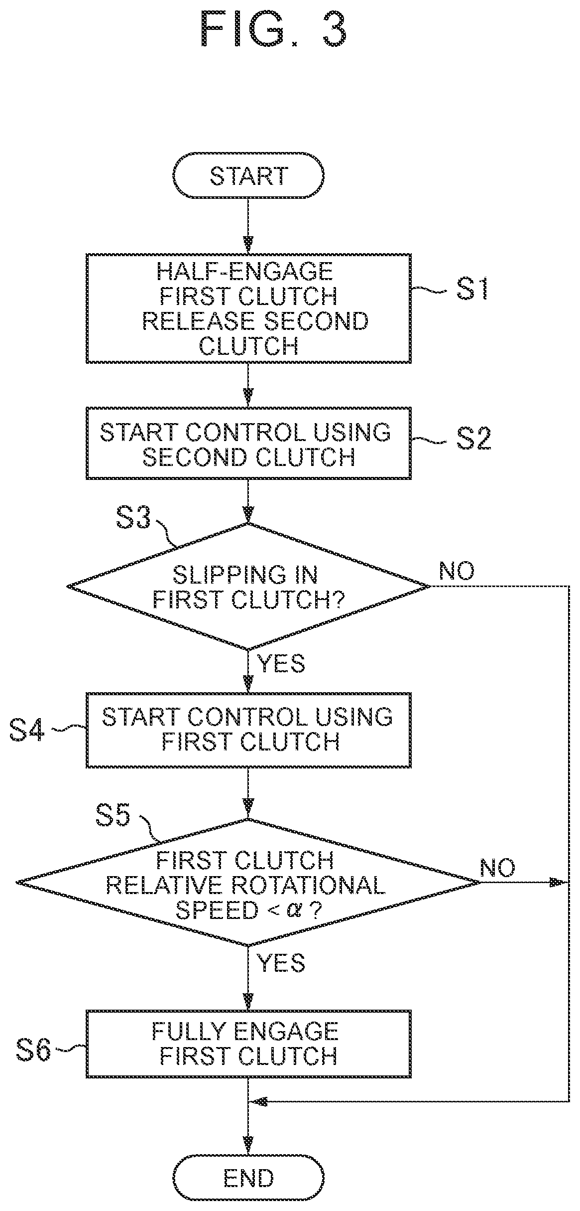
[0019]According to the control system according to the first aspect of the disclosure and the control method according to the second aspect of the disclosure, when the vehicle is started from a stopped state, the first clutch and the second clutch are controlled in coordination with each other. More specifically, while the vehicle is in the stopped state, the first clutch, which is a fully dipped clutch (oil-bath type clutch that is entirely filled with or immersed in the oil) and thus has low responsiveness, is placed in a half-engaged state in advance, and the start control is started, using the second clutch that is highly responsive to accelerator operation. Namely, the acceleration response in the initial period of starting is secured through control of the second clutch. Then, when the clutch torque capacity of the second clutch increased according to the accelerator operation exceeds the clutch torque capacity of the first clutch that is in the half-engaged standby state (in other words, when slipping occurs in the first clutch), the start control of the vehicle is switched from the first mode using the second clutch to the second mode using the first clutch. Namely, once the initial response is secured by the second clutch, the second clutch is immediately fully engaged so as not to do friction work, since the second clutch has relatively low durability, and the subsequent stage of the start control of the vehicle is performed through control of the first clutch. Since the first clutch is placed in the half-engaged standby state in advance, delay in the response is eliminated or reduced when the start control is switched from the first mode using the second clutch to the second mode using the first clutch, though the first clutch has relatively low responsiveness. Further, the durability of the clutches under the start control is less likely or unlikely to be reduced since the first clutch has high durability. With the control system of the disclosure, both the acceleration performance of the vehicle and the durability of each clutch can be ensured. Namely, unlike the known arrangement with which only the acceleration performance is ensured, or only the durability is ensured, it is possible to curb reduction of the durability of each clutch while ensuring sufficient acceleration response of the vehicle.

Problems solved by technology

Thus, when the wet clutch is used as the starting device, the load of the engine caused by the drag torque is increased.
In particular, when the vehicle is started, under a condition where the vehicle is left in a soaked state for a long period of time, or the viscosity of the oil is high at an extremely low temperature, the drag torque becomes extremely large, and the starting performance of the vehicle may deteriorate.
Thus, deterioration of the acceleration performance may not be sufficiently curbed.

Method used


Image

  • Control system and control method for vehicle
  • Control system and control method for vehicle
  • Control system and control method for vehicle

Examples


Embodiment Construction

[0025]One embodiment of the disclosure will be described with reference to the drawings. The embodiment described below is a mere example of what embodies this disclosure, and is not intended to limit the disclosure.

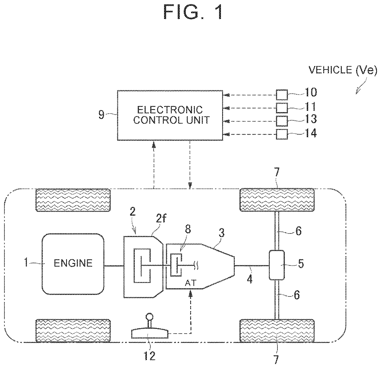
[0026]FIG. 1 shows one example of a vehicle Ve to which this disclosure can be applied. The vehicle Ve shown in FIG. 1 includes an engine (ENG) 1 as a drive power source, and an automatic transmission (AT) 3 coupled to the output side of the engine 1, via a first clutch 2. A propeller shaft 4 is coupled to the output side of the automatic transmission 3. The propeller shaft 4 is coupled to drive wheels 7, via a differential gear set 5 as a final reduction gear, and right and left drive axles 6. In the example shown in FIG. 1, the vehicle Ve is constructed as a rear-wheel-drive vehicle that generates drive power by transmitting power generated by the engine 1 to the drive wheels 7 as rear wheels. The vehicle Ve in the embodiment of the disclosure may be a front-wheel-driv...


PUM


Abstract

The disclosure is concerned with control system and control method, for a vehicle including a driving power source, drive wheels, a first clutch, and a second clutch. An electronic control unit, which is included in the control system, places the first clutch in a half-engaged state with a predetermined clutch torque capacity, when the vehicle is started, performs start control in a first mode using the second clutch, by gradually increasing a clutch torque capacity of the second clutch from a released state, and switches the start control from the first mode using the second clutch to a second mode using the first clutch, when the increased clutch torque capacity of the second clutch reaches the clutch torque capacity of the first clutch.

Description

CROSS-REFERENCE TO RELATED APPLICATION[0001]This application claims priority to Japanese Patent Application No. 2019-205527 filed on Nov. 13, 2019, incorporated herein by reference in its entirety.BACKGROUND1. Technical Field[0002]The disclosure relates to control system and control method for controlling a vehicle on which an automatic transmission is installed, and in particular to vehicular control system and control method for controlling operation of clutches, when the vehicle is started.2. Description of Related Art[0003]Generally, in a vehicle on which an automatic transmission is installed, a torque converter that serves as a starting device is provided between an engine and the automatic transmission. The use of the torque converter makes it possible to amplify output torque of the engine in a low-rotational-speed range, and provide large drive power for starting. Then, the vehicle can be smoothly started, through smooth power transmission via fluid. In the meantime, a vehi...

Claims


Application Information

Patent Timeline
Patent Type & Authority Patents(United States)
IPC IPC(8): F16D48/08F16D13/52F16D13/72F16D21/00F16D13/74F16D21/08
CPCF16D48/08F16D13/52F16D13/72F16D21/00F16D13/74F16D21/08F16D2500/1045F16D2500/1085F16D2500/10412F16D2500/30404F16D2500/30406F16D2500/30412F16D2500/30426F16D2500/3109F16D2500/3111F16D25/06F16D25/12F16H63/3026F16H2063/303F16D2500/1026F16D2500/50239F16D2500/50206F16D2500/3144F16D2500/31466F16D2500/50296F16D2500/50808F16D2500/50858F16D2500/525F16D2500/70426
Inventor WATANABE, HIDEOMIZUTO, RYOSUKE
Owner TOYOTA JIDOSHA KK
Learn More