
Under-roof antenna modules for vehicle

a technology for under-roof antennas and vehicles, applied in the field of under-roof antenna modules for vehicles, can solve the problems of limited area, inability to implement a 44 mimo antenna solution, and limited available area, and achieve the effect of maximizing isolation

Active Publication Date: 2020-01-02
ADVANCED AUTOMOTIVE ANTENNAS
View PDF0 Cites 5 Cited by
  • Summary
  • Abstract
  • Description
  • Claims
  • Application Information

AI Technical Summary

Benefits of technology

This patent text describes an under-roof antenna module for vehicles that can improve the performance of a transceiver and increase efficiency of reception in a MIMO system. By placing the transceiver at the perforations in the frame, it is possible to maximize its performance. The module can be integrated into the roof of the vehicle, allowing for seamless integration and maximizing isolation. Additionally, a cavity in the roof can minimize interference with other parts of the vehicle and devices inside. The technical effects of this patent are improved performance and efficiency of the under-roof antenna module for vehicles.

Problems solved by technology

Its available area is generally limited.
However, it is a visible location, and furthermore the available area is limited so, for instance, it is not feasible to implement a 4×4 MIMO antenna solution in the shark fin.
However, performance of the antennas in the dashboard can be degraded if a thermal layer is used and especially for GNSS antennas because the GNSS antenna diagram pattern is pointing to the zenith (towards the GNSS satellites in the sky).

Method used


Image

  • Under-roof antenna modules for vehicle
  • Under-roof antenna modules for vehicle
  • Under-roof antenna modules for vehicle

Examples


Embodiment Construction

[0032]The following description is merely exemplary in nature and is not intended to limit the present disclosure, its application or uses.

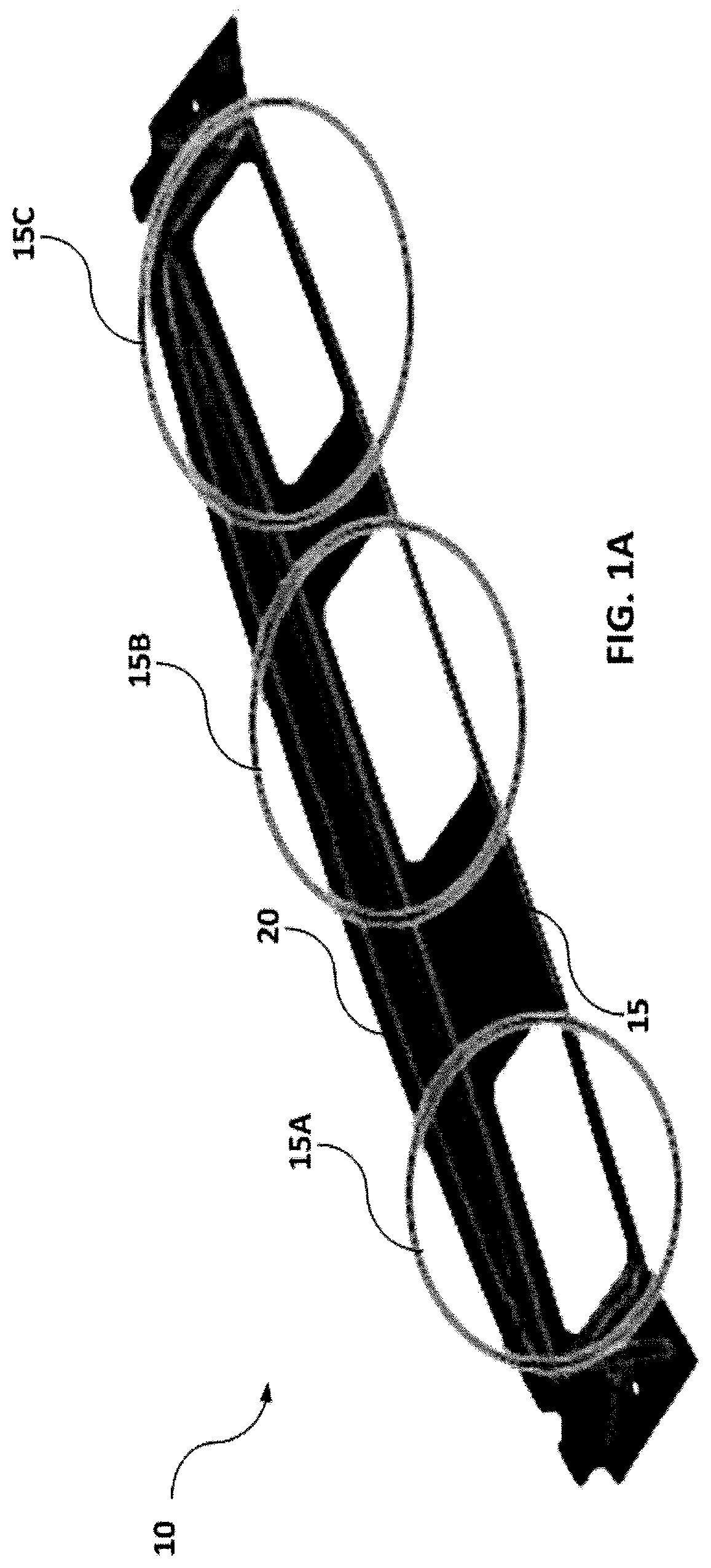
[0033]FIG.1A schematically illustrates a frame for an under-roof module according to an example. Frame 10 may have an elongated form and may comprise a first part 15 and a second part 20. The two parts may define two profile steps at different levels. One level may correspond to a recession level of a roof of a vehicle and the other level may correspond to the roof level of the vehicle. The elongated frame may be configured to be mounted in a cavity of the vehicle part, e.g. roof, hood (bonnet), trunk (boot) of a vehicle. The height difference between the two levels may be selected to allow for the collocation of one or more transceivers on the lower level along the frame. The first part 15 may comprise perforations or holes 15A, 15B and 15C. The perforations may be substantially rectangular.

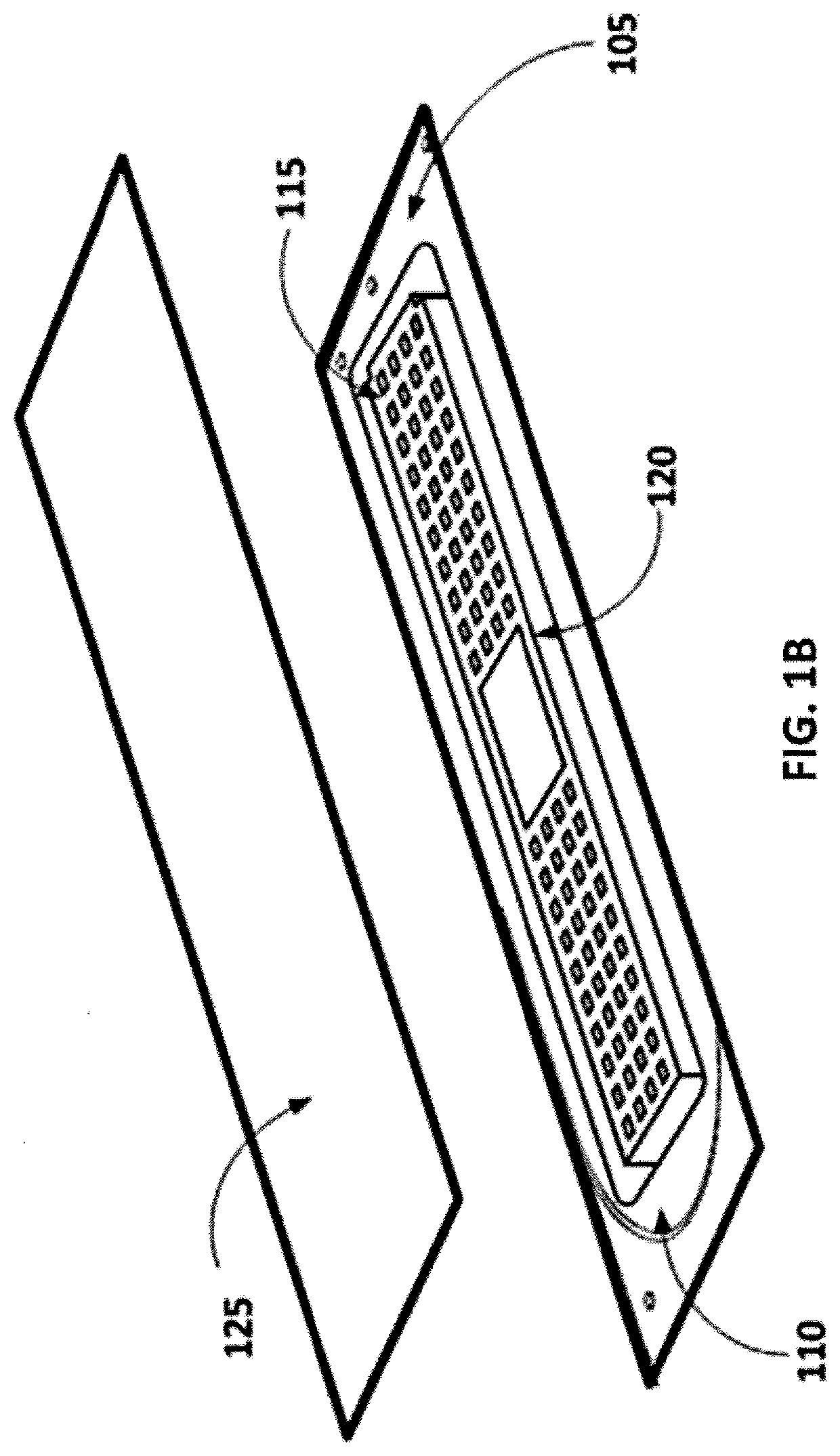
[0034]FIG. 1B schematically illustrates an antenna modu...


PUM


Abstract

An under-roof antenna module for a vehicle includes a metallic frame with at least one perforation, and at least one transceiver. The at least one transceiver is arranged at portions of the frame proximal to the at least one perforation.

Description

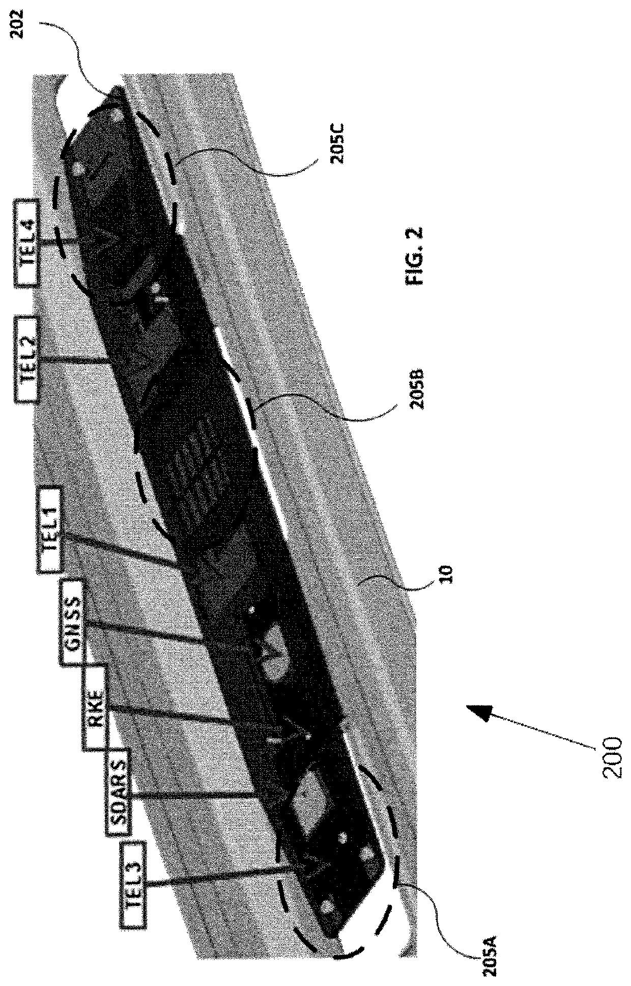
CROSS-REFERENCE TO RELATED APPLICATIONS[0001]This patent application claims priority to European Provisional Patent Application No. 18382483.8, filed Jun. 29, 2018, which is incorporated herein by reference in its entirety.INTRODUCTION[0002]The present disclosure relates to antenna modules, and more particularly, to under-roof antenna modules for vehicles.[0003]A typical vehicle may host antennas for various wireless technologies, such as telephony (up to 4 antennas if Multiple Input Multiple Output (MIMO) antennas are used), global navigation satellite system (GNSS), Satellite Digital Audio Radio Service (SDARS), Remote Key Entry (RKE), AM / FM / Digital Audio Broadcasting (DAB) etc. The number of antennas that may possibly be hosted in a vehicle is increasing with time. Traditionally, antennas are integrated in different locations of a vehicle. Such locations may vary. Example locations include the external rear view mirror, the Shark fin, the windscreen, the bumpers, the rain sensor ...

Claims


Application Information

Patent Timeline
Patent Type & Authority Applications(United States)
IPC IPC(8): H01Q1/32
CPCH01Q1/3275H01Q1/3241H01Q1/3291H01Q1/48H01Q21/28
Inventor ORTIGOSA, ENRIQUE MARTINEZ
Owner ADVANCED AUTOMOTIVE ANTENNAS
Learn More